A marking hole drilling jig for plunger

A marking and hole drilling technology, applied in the direction of drilling dies, clamping, and manufacturing tools for workpieces, can solve the problems of affecting processing efficiency, increasing labor intensity, time-consuming and laborious, etc., to reduce labor intensity, improve processing efficiency, Precisely positioned effects

Active Publication Date: 2016-02-03
无锡威孚马山油泵油嘴有限公司
View PDF5 Cites 0 Cited by
  • Summary
  • Abstract
  • Description
  • Claims
  • Application Information

AI Technical Summary

Problems solved by technology

[0002] In order to distinguish the various models of the plunger parts, in the prior art, the marking holes are usually drilled on the plunger parts. Since the marking holes are arranged at intervals, in the prior art, after drilling a marking hole, the post is usually drilled. The plug moves again for a certain distance to drill the next marked hole. This drilling method not only increases the labor intensity, but also greatly wastes time, is time-consuming and laborious, and affects the processing efficiency.

Method used


Image

  • A marking hole drilling jig for plunger
  • A marking hole drilling jig for plunger

Examples


Embodiment Construction

[0017] The specific implementation manner of the present invention will be described below in conjunction with the accompanying drawings.

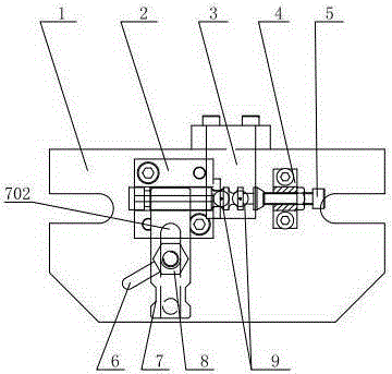
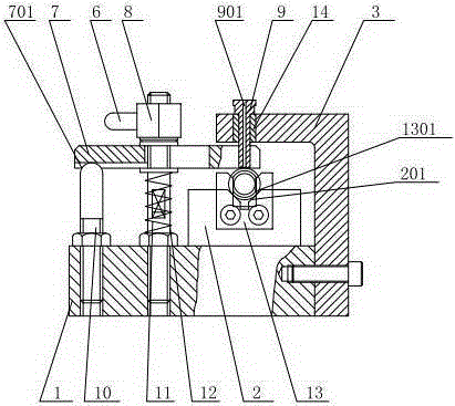
[0018] Such as figure 1 , figure 2 As shown, a marking hole drilling jig for plunger parts includes a bottom plate 1, one end of a double-ended screw 12 is screwed to the bottom plate 1 and locked by a nut (not shown in the figure), and the other end penetrates the pressure plate 7 And be screwed in locking nut 8, locking nut 8 is welded with locking handle 6, in the bottom of pressing plate 7, be positioned at the outer periphery of double-ended screw rod 12 and also sleeve spring 11. Have groove 701 and waist-shaped hole 702 on pressing plate 7; Be positioned at the side of double-ended screw rod 12, also install top post 10 on bottom plate 1, one end of top post 10 stretches out bottom plate 1 and opens with pressing plate 7 Groove 701 abuts; drill sleeve positioning plate 3 is installed on one side of base plate 1, drill sleeves 9 a...


PUM


Abstract

The invention relates to a fixture for drilling mark holes in plunger parts. The fixture comprises a bottom plate. One end of a double-thread screw is screwed to the bottom plate; the other end of the double-thread screw penetrates a press plate and is screwed to a locknut. An ejector post is disposed on the bottom plate on one side of the double-thread screw; one end of the ejector post extends out of the bottom plate and is abutted to the press plate. A drill bushing positioning plate is disposed on one side of the bottom plate; drill bushings which are spaced are disposed in the drill bushing positioning plate through bushings; each drill bushing is provided with a drilling hole inside; a positioning block and a positioning seat are also fixedly connected onto the bottom plate. The fixture is simple in structure and convenient to mount; a plunger part is clamped and locked and is accurately positioned through a positioning plate, the positioning block and a positioning rod, multiple mark holes are machined once by extending a drill bit into the symmetric drill bushings on the drill bushing positioning plate, machining efficiency is greatly improved, production cost is saved for enterprises, secondary clamping is avoided, and labor intensity is reduced for workers.

Description

technical field [0001] The invention relates to a tooling fixture, in particular to a marking hole drilling fixture for a plunger. Background technique [0002] In order to distinguish the various models of the plunger parts, in the prior art, the marking holes are usually drilled on the plunger parts. Since the marking holes are arranged at intervals, in the prior art, after drilling a marking hole, the post is usually drilled. The plug moves a certain distance again to carry out the drilling of the next marking hole. This drilling method not only increases the labor intensity, but also greatly wastes time, takes time and effort, and affects the processing efficiency. Contents of the invention [0003] In view of the above-mentioned existing problems, the applicant has made researches and improvements, and provides a marking hole drilling jig for plunger parts, which effectively realizes the drilling of the marking holes in place at one time, and greatly improves the proc...

Claims


Application Information

Patent Timeline
Patent Type & Authority Patents(China)
IPC IPC(8): B23Q3/06B23B47/28
CPCB23B47/28
Inventor 徐俊伟
Owner 无锡威孚马山油泵油嘴有限公司
Why Eureka
Try Eureka