Yarn traction device

A traction equipment and spinning technology, applied in the production of complete sets of equipment for artificial threads, drawing spinning, textiles and papermaking, etc., can solve the problems of not being able to fully reduce operating costs, not be able to suppress power consumption, etc., and achieve improvement Maintainability, simple structure, and efficient guidance

Active Publication Date: 2014-06-04
TMT MACHINERY INC
View PDF6 Cites 9 Cited by
  • Summary
  • Abstract
  • Description
  • Claims
  • Application Information

AI Technical Summary

Problems solved by technology

However, when there is a low-temperature air area in the incubator, the power consumption of the rollers placed in the low-temperature air area cannot be suppressed, and there is a problem that the running cost cannot be sufficiently reduced.

Method used


Image

  • Yarn traction device
  • Yarn traction device
  • Yarn traction device

Examples


Embodiment Construction

[0035] First, a spinning drawing device 100 according to an embodiment of the present invention will be described.

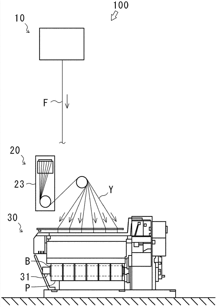
[0036] figure 1 It is a figure which shows the whole structure of the spinning drawing-up apparatus 100. In general, spinning drawing equipment is divided into equipment for producing fully drawn yarn (FDY) in which the yarn is completely drawn, and equipment for producing partially oriented yarn (POY) in which the yarn is partially drawn. The spinning take-up facility 100 of this embodiment is a facility for producing fully drawn yarn (FDY).

[0037] The spinning take-up device 100 spins out the single fiber F, makes the yarn Y formed by bundling the single fiber F into a desired characteristic, and winds the yarn Y to form a package P. The spinning take-up facility 100 is mainly composed of a spinning device 10 , a godet roll group 20A, and a winding device 30 .

[0038] The spinning device 10 spins a plurality of single fibers F. The synthetic fiber raw m...


PUM


Abstract

The invention provides a yarn traction device which guides high temperature in a heat preservation box to a low temperature air area and thus restrains power consumption of rollers in the lower temperature air area and further reduces the operation cost. The yarn traction device (100) comprising a plurality of rollers (21 and 22) which deliver yarn (Y) through rotation comprises the heat preservation box (23) receiving the rollers (21 and 22), and an air pipe channel (24) installed in the heat preservation box (23), wherein the air pipe channel (24) guides high temperature air in the heat preservation box (23) to a low temperature air area in the heat preservation box (23).

Description

technical field [0001] The present invention relates to the technology of spinning drawing equipment. In more detail, it relates to the technology of the spinning drawing-up facility which can reduce running cost. Background technique [0002] Conventionally, there is known a spinning take-up device provided with a plurality of rollers that feed out a yarn by rotation (for example, Patent Document 1). Such a spinning take-up device includes a roll for heating the yarn to a drawing temperature (hereinafter referred to as “heating roll”) and a roll for heating the yarn to a tempering temperature (hereinafter referred to as “conditioning roll”). [0003] However, there is known a spinning take-up device in which a heating roll and a tempering roll are accommodated in a single thermal box (for example, Patent Document 2). This is to reduce the power consumption of the electric heater built in each roll by storing the heating roll and the tempering roll in the thermal insulatio...

Claims


Application Information

Patent Timeline
Patent Type & Authority Applications(China)
IPC IPC(8): D01D5/16D01D10/02
CPCD01D10/02D01D13/02D01D7/00D02J13/00
Inventor 桥本欣三杉山研志
Owner TMT MACHINERY INC
Why Eureka
Try Eureka