Micro cantilever beam deflection scanning system and method for micro cantilever beam array sensor based on multi-angle plane transmitting mirrors
An array sensor and micro-cantilever technology, applied in the field of micro-cantilever deflection scanning system, can solve the problems of particle motion, detection data error, inability to guarantee laser beam consistency, etc., achieve high accuracy, eliminate system errors, and avoid optical paths the effect of interference
- Summary
- Abstract
- Description
- Claims
- Application Information
AI Technical Summary
Problems solved by technology
Method used
Image

Examples
Embodiment 1
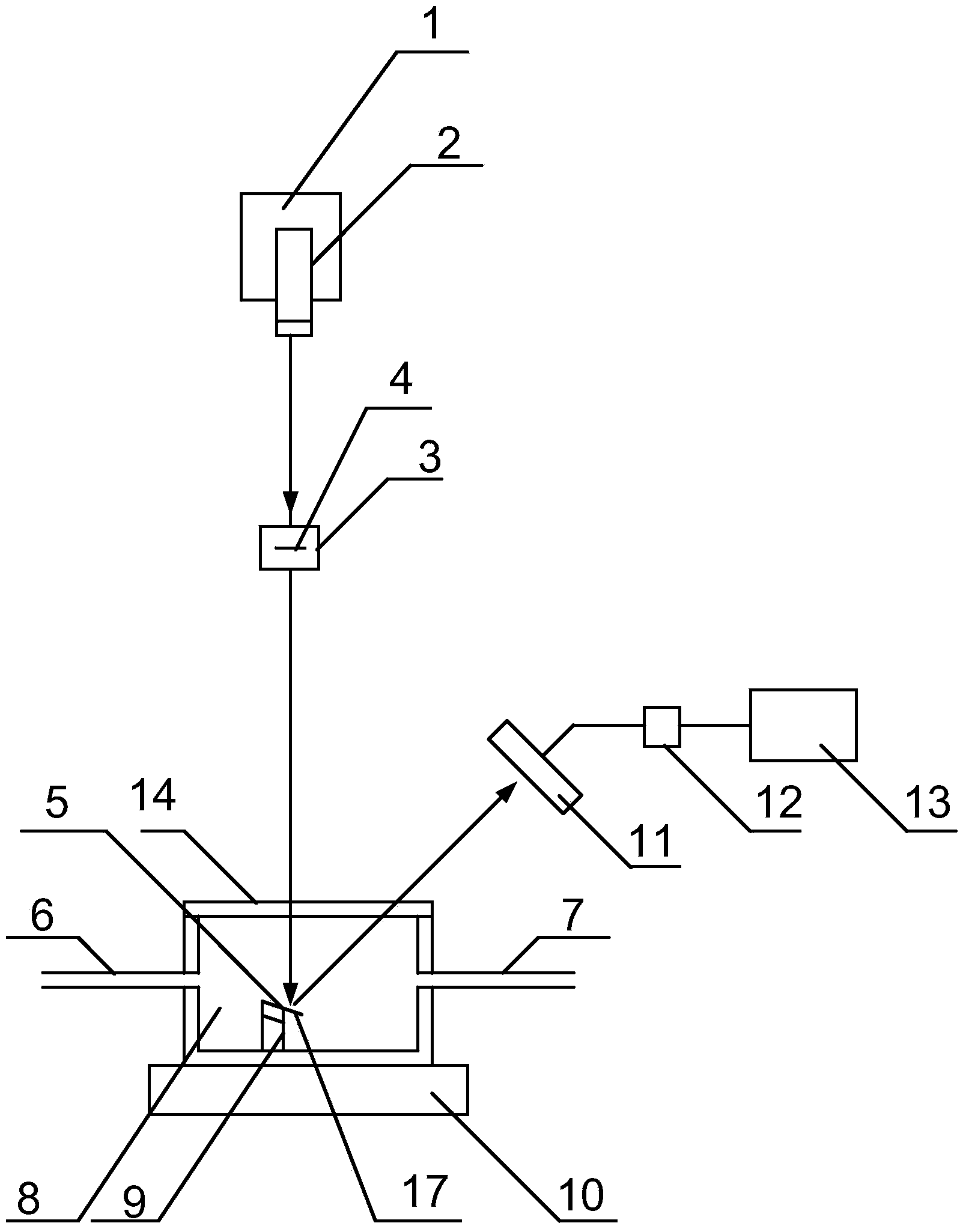
[0044] Such as figure 1 As shown, the micro-cantilever deflection scanning system includes:
[0045] A laser 2 for emitting laser beams vertically downward; the laser 2 is set on a movable platform 1 whose initial position can be adjusted; the laser is a semiconductor laser, and the laser light source is a monochromatic light source within the range of 632nm-780nm.
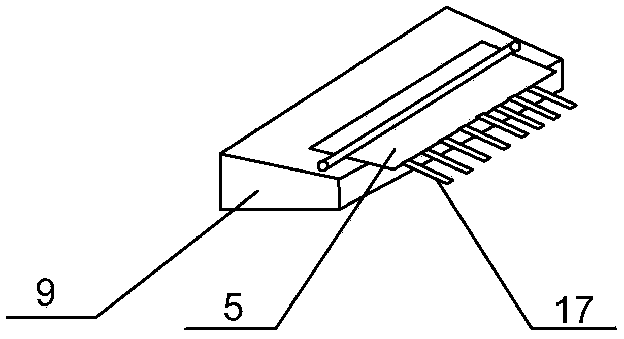
[0046] A line-arranged plane transmission mirror group fixed in front of the horizontal displacement platform 3 sides, the plane transmission mirror group consists of the first plane transmission mirror 41, the second plane transmission mirror 42 ... and the Nth plane transmission mirror 4N from left to right Composition, N is equal to the number M of micro-cantilever beams on the micro-cantilever beam array of the sensor to be tested. The sensor micro-cantilever beam array is composed of the first micro-cantilever beam 51, the second micro-cantilever beam 52 ... and the 5th M micro-cantilever beam from left to ri...
Embodiment 2
[0059] The line-arranged planar transmission lens group fixed on the horizontal displacement platform in Embodiment 1 is replaced by being fixed on the horizontal rotation platform 15, and the array is changed to be arranged in a circle around the rotation axis of the rotation platform, and the horizontal rotation platform is A light-shielding plate with round holes, which are respectively located directly in front of each plane transmission mirror. The size of the round hole allows the laser to irradiate the plane transmission mirror, and the scanning of the microbeam can be realized after passing through the plane transmission mirror; Figure 5a , 5b shown.
Embodiment 3
[0061] The scanning method of the scanning system of embodiment 1 or 2, comprises the steps:
[0062] 1) Place the micro-cantilever array sensor to be tested on the substrate clamping platform in the solvent pool. The substrate clamping platform arranges the micro-cantilever beam array in an oblique direction. The solvent pool is airtight, with a transparent glass window on the top, and the solvent The pool controls the entry and exit of solvents through the inlet pipe and outlet pipe;
[0063] 2) Adjust and fix the initial position of the laser, and at the same time adjust the initial position of the horizontal displacement platform or the horizontal rotation platform, so that the only horizontally set plane transmission mirror in the plane transmission lens group is located directly below the laser, and adjust the initial position of the solvent pool, Make the micro-cantilever in the micro-cantilever array sensor corresponding to the only horizontally arranged plane transmis...
PUM
| Property | Measurement | Unit |
|---|---|---|
| Thickness | aaaaa | aaaaa |
Abstract
Description
Claims
Application Information
 - R&D
- Intellectual Property
- Life Sciences
- Materials
- Tech Scout
- Unparalleled Data Quality
- Higher Quality Content
- 60% Fewer Hallucinations
Browse by: Latest US Patents, China's latest patents, Technical Efficacy Thesaurus, Application Domain, Technology Topic, Popular Technical Reports.
© 2025 PatSnap. All rights reserved.Legal|Privacy policy|Modern Slavery Act Transparency Statement|Sitemap|About US| Contact US: help@patsnap.com