Driving system and method of backlight source

A driving system and driving method technology, applied in the direction of instruments, static indicators, etc., can solve the problems of increasing the complexity of system circuits and consuming driving costs, and achieve the effects of reducing the number, saving driving costs, and reducing complexity

Active Publication Date: 2014-06-04
HISENSE VISUAL TECH CO LTD
View PDF5 Cites 18 Cited by
  • Summary
  • Abstract
  • Description
  • Claims
  • Application Information

AI Technical Summary

Problems solved by technology

[0005] because figure 1 The prior art shown requires a corresponding driving circuit for each LED backlight, so as the number of backlight partitions increases, the driving system of the LED backlight also needs to be equipped with a corresponding number of driving circuits, which not only increases the system circuit Complexity, and consumes a lot of driving costs

Method used


Image

  • Driving system and method of backlight source
  • Driving system and method of backlight source
  • Driving system and method of backlight source

Examples


Embodiment 1

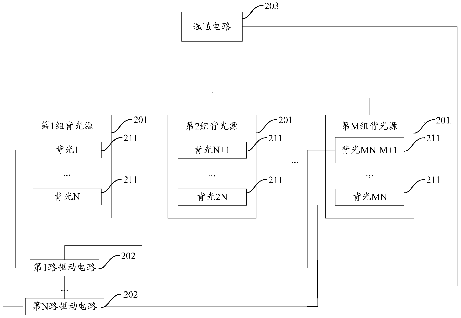
[0032] refer to figure 2 , which provides a structural diagram of the driving system of the backlight provided in Embodiment 1 of the present application, which may specifically include:

[0033] M groups of backlights 201, wherein each group of backlights may specifically include at least N backlights 211; said M is an integer greater than or equal to 2;

[0034] N-way driving circuits 202, wherein the N-way backlights 211 in each group of backlight sources are respectively connected to the N-way driving circuits 202;

[0035] The gating circuit 203 is connected to the M groups of backlight sources 201, and is used to time-divisionally select a group of backlight sources 201 in the M groups of backlight sources 201 to be driven to emit light by the N-way driving circuit 202 within a scanning period. .

[0036] The embodiments of the present application can be applied to various liquid crystal display devices with a dynamic backlight function.

[0037] In order to reduce t...

Embodiment 2

[0056] On the basis of the first embodiment above, the driving system of the backlight in this embodiment may further include the following optional technical solutions.

[0057] The peak current value provided by each drive circuit 202 of this embodiment for each backlight 211 is greater than the peak current value during non-time-division scanning.

[0058] Since each group of backlight sources is turned on in M ​​scanning intervals in one scanning period, if the peak current value during non-time-sharing scanning is used at this time, the number of backlight sources lit per unit time will decrease, so In order to improve the brightness of the entire liquid crystal screen, each drive circuit 202 of the present embodiment increases the peak current value provided for each backlight 211 to make it greater than the peak current value during non-time-sharing scanning, where the non-time-sharing scanning is State-of-the-art scanning methods.

[0059] In a preferred embodiment of...


PUM


Abstract

The invention provides a driving system and method of a backlight source. The system specifically comprises M sets of backlight sources, N paths of driving circuits and a gating circuit, wherein each set of the backlight sources comprises N paths of backlight, M is an integer larger than or equal to 2, the N paths of backlight in each set of the backlight sources are connected with the N paths of the driving circuits respectively, and the gating circuit is connected with the M sets of the backlight sources and used for carrying out time sharing option on one set of the backlight sources in the M sets of the backlight sources so as to enable the one set of the backlight sources in the M sets of the backlight sources to be driven by the N paths of the driving circuits to emit light in one scanning cycle. According to the system and method, the number of the driving circuits can be reduced.

Description

technical field [0001] The present application relates to the technical field of backlight driving, in particular to a backlight driving system and method. Background technique [0002] In the existing liquid crystal display device, the liquid crystal panel needs the light source provided by the backlight to display images normally, and light emitting diode (LED, Light Emitting Diode) has become the mainstream of the backlight. [0003] At present, the scanning (scanning backlight) technology of backlight is often used to improve the characteristics of backlight and the quality of moving images. The principle is to divide the liquid crystal display device into multiple areas according to the horizontal area. Turn off the corresponding backlight during the conversion period; because the display of liquid crystal molecules is unstable during the conversion period, the image display is blurred. When the backlight corresponding to the liquid crystal molecules is turned off, the ...

Claims


Application Information

Patent Timeline
Patent Type & Authority Applications(China)
IPC IPC(8): G09G3/36G09G3/34
Inventor 张玉欣郝卫
Owner HISENSE VISUAL TECH CO LTD
Why Eureka
Try Eureka