Light-emitting keyboard

A technology of light-emitting keyboards and light-emitting components, which is applied to electrical components, electrical switches, circuits, etc., can solve the problems of poor light use efficiency, unclear visibility, and inability to effectively reduce the thickness of the light-emitting keyboard 1.

Inactive Publication Date: 2014-06-04
PRIMAX ELECTRONICS LTD
View PDF15 Cites 56 Cited by
  • Summary
  • Abstract
  • Description
  • Claims
  • Application Information

AI Technical Summary

Problems solved by technology

[0009] 1. Although the reflector 11 can assist the light beams scattered downward by multiple light guide points 121 to reflect upward, the material of the reflector 11 of the existing light-emitting keyboard 1 can still allow a little light beam to penetrate, so part of it is made up of multiple light guides. The light beam scattered downward by point 121 will penetrate the reflector 11 and cause the loss of light quantity
[0010] 2. Although the light beam can be diffused to the entire light guide plate 12 when it enters the light guide plate 12, part of the light beam has been reflected out of the light guide plate 12 due to the light guide point 121 that is closer to the side light-emitting element 16, so that the light guide plate 12 The amount of light in the area farther from the side light emitting element 16 is not as sufficient as the area closer to the side light emitting element 16
[0011] 3. Since the scissor-type connecting element 153 has a relatively long operation stroke, the light-emitting keyboard 1 must have enough space to enable the scissor-type connecting element 153 to operate normally. However, the thickness of the light-emitting keyboard 1 cannot be effectively reduced, so that Unable to meet the appearance demands of today's electronic products towards light, thin and short development
[0012] As can be seen from the description of the first and second points above, although the existing light-emitting keyboard 1 is able to make the plurality of keys 15 emit light through the cooperation of the side-type light-emitting element 16 and the light guide plate 12, the light use efficiency is not high. good
Based on this, under the thinking

Method used


Image

  • Light-emitting keyboard
  • Light-emitting keyboard
  • Light-emitting keyboard

Examples


Embodiment Construction

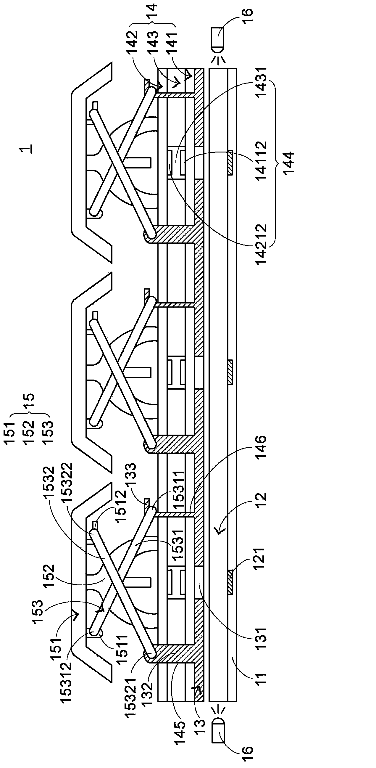
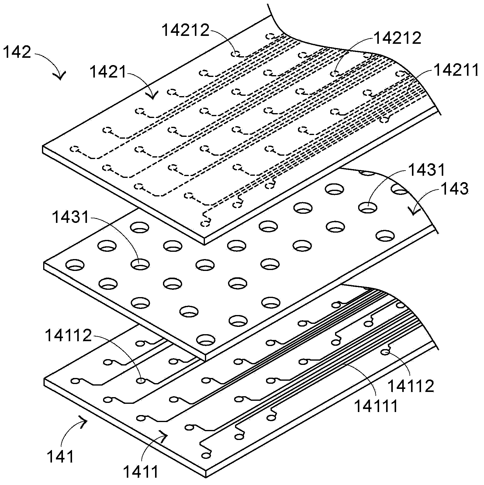
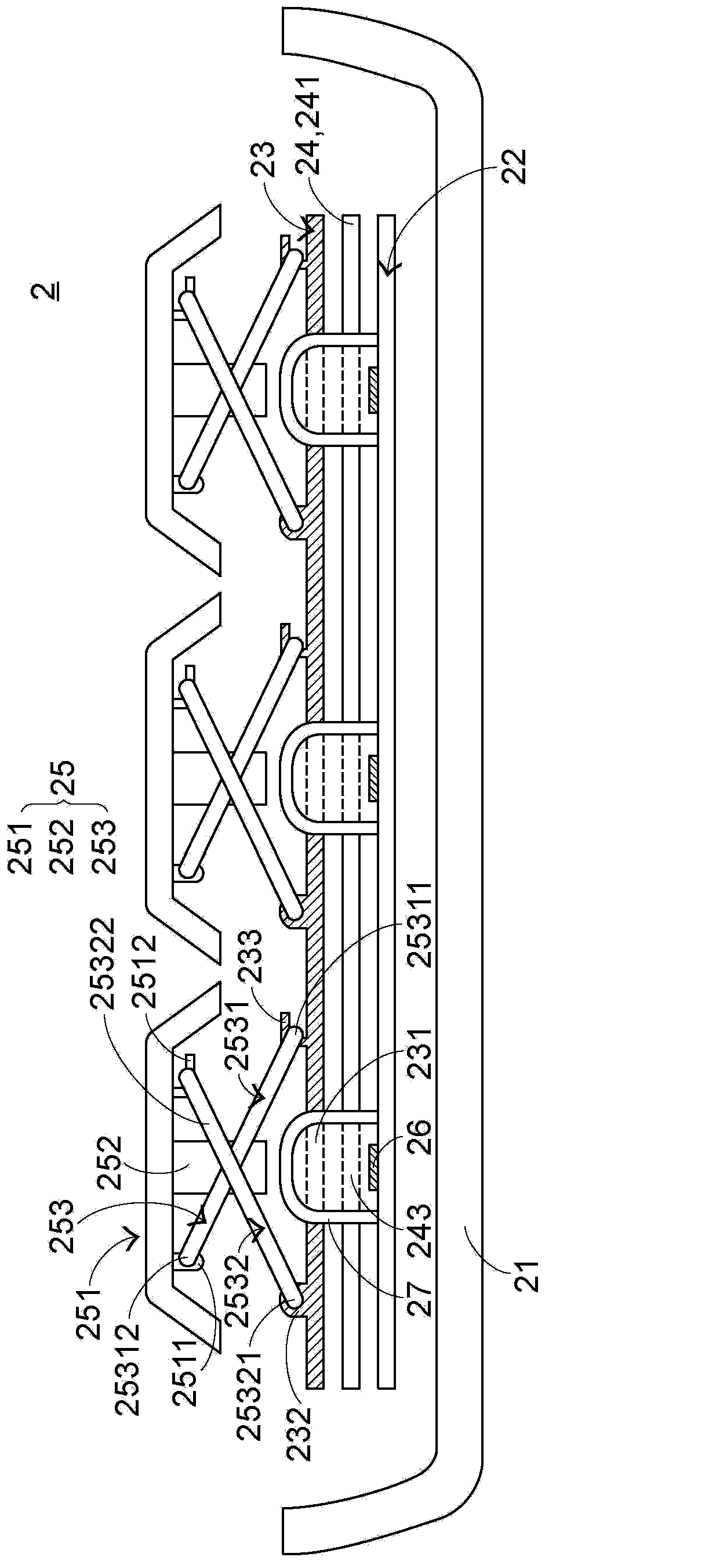
[0115] see image 3 and Figure 4 , image 3 It is a side view of the structure of the luminous keyboard in the first preferred embodiment of the present invention, Figure 4 for image 3 The structure diagram of the sensing circuit layer and the driving circuit board of the light-emitting keyboard shown. The luminous keyboard 2 includes a base 21, a light-emitting element driving circuit board 22, a sensing circuit layer 24, a support plate 23, and a plurality of keys 25 from bottom to top, and the luminous keyboard 2 also includes a plurality of buttons corresponding to the plurality of keys 25. Direct-type light-emitting elements 26 and a plurality of light-transmitting elastic bodies 27 corresponding to the plurality of direct-type light-emitting elements 26; wherein, the base 21 is used to carry a light-emitting element driving circuit board 22, a sensing circuit layer 24, a support plate 23, and a plurality of keys 25. A plurality of direct-type light-emitting elemen...


PUM


Abstract

The invention provides a light-emitting keyboard comprising multiple direct illumination-type light-emitting elements, an induction circuit layer, multiple keys and multiple light-transmitting elastic bodies. When the keys are close to the induction circuit layer, the induction circuit layer correspondingly generates a non-contact type key signal. Besides, each direct illumination-type light-emitting element is corresponding to one key and arranged below the corresponding key. Each light-transmitting elastic body is corresponding to one direct illumination-type light-emitting element and arranged between the corresponding direct illumination-type light-emitting element and the corresponding key. Light beams of each direct illumination-type light-emitting element penetrate through the corresponding light-transmitting elastic body and then are projected to the corresponding key. According to the design of the light-emitting keyboard, the direct illumination-type light-emitting elements are directly arranged below the keys, and the elastic bodies used for returning key caps to original positions and providing hand feeling for a user are designed in a light-transmitting way so that the light beams provided by the direct illumination-type light-emitting elements can be projected to the keys after directly penetrating through the light-transmitting elastic bodies, and thus use efficiency of light is effectively enhanced.

Description

technical field [0001] The invention relates to a keyboard, in particular to a keyboard with a light-emitting function. Background technique [0002] In recent years, due to the rapid development of the information industry, many users may use portable information devices in different environments, such as notebook computers, mobile phones or personal digital assistants. In a low-light environment, users may not be able to clearly see the numbers and characters marked on the keyboard keys, thus causing difficulties in operation, and in severe cases, may even cause vision loss due to barely recognizing the key marks. Therefore, the launch of the luminous keyboard can improve the inconvenience of the user using the keyboard in places with insufficient light. What's more, by means of different lighting configurations, the information device using the lighting keyboard can look more beautiful, thereby increasing its sales. [0003] see figure 1 , which is a structural cross-s...

Claims


Application Information

Patent Timeline
IPC IPC(8): H01H13/83
Inventor 陈仲渊
Owner PRIMAX ELECTRONICS LTD
Why Eureka
Try Eureka