Pipe-bending machine

A technology of pipe bending machine and pipe bending shaft, which is applied in the field of long overall length or softer heat dissipation pipes, where there are many production elbows, and can solve the problems that the bending cannot be completed smoothly, so as to reduce the working intensity and control the process simple effect

Active Publication Date: 2014-06-11
合肥盛邦电器有限公司
View PDF7 Cites 5 Cited by
  • Summary
  • Abstract
  • Description
  • Claims
  • Application Information

AI Technical Summary

Problems solved by technology

[0002] The structure of the existing pipe bending machine is: a pushing device is provided on a platform to transport the pipe fittings, and the pipe fittings are pushed along the rails to the pipe bending device on the platform by using the pushing device. Bending into a serpentine tube of the required

Method used


Image

  • Pipe-bending machine
  • Pipe-bending machine
  • Pipe-bending machine

Examples


Embodiment Construction

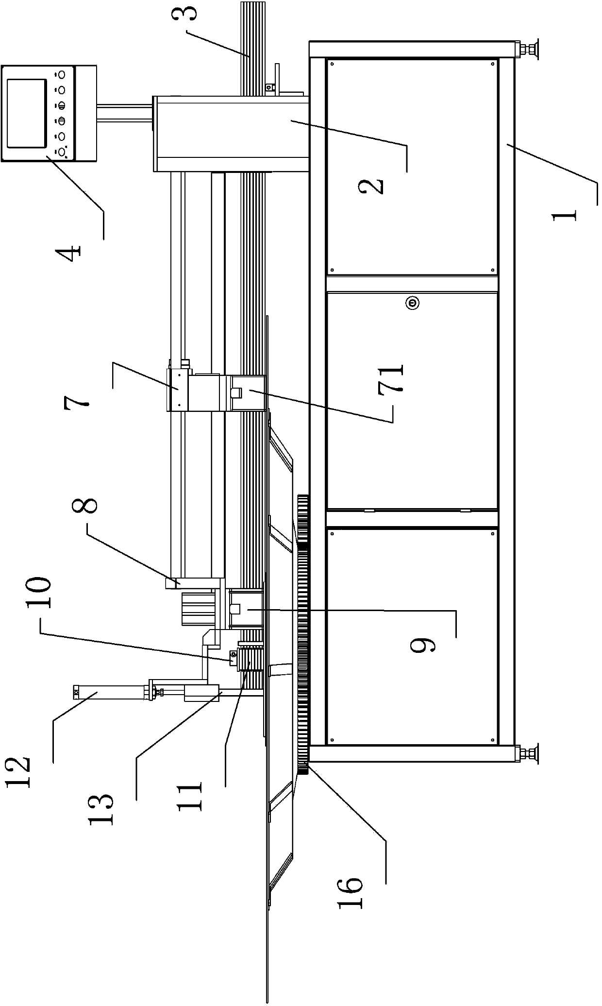
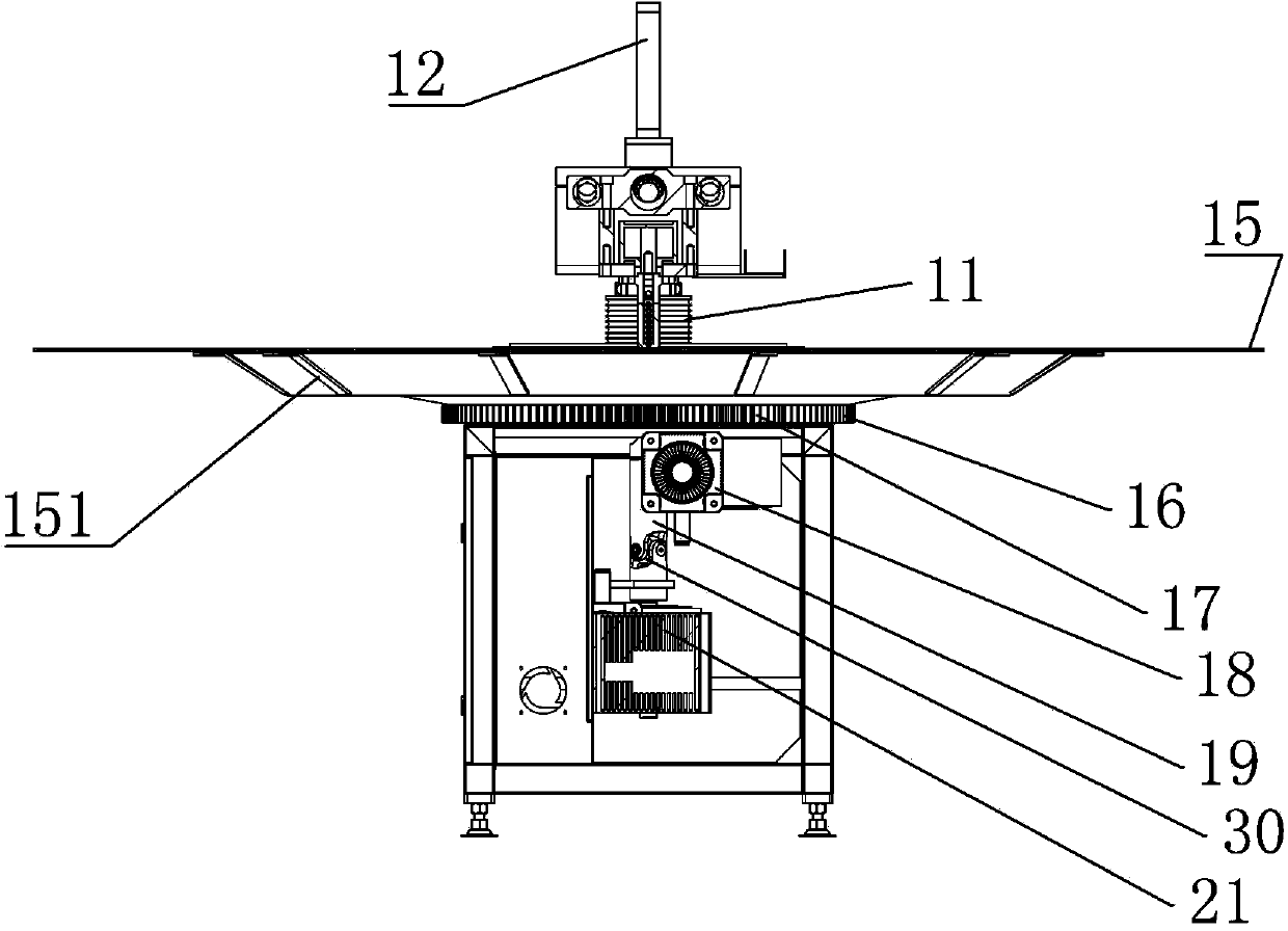
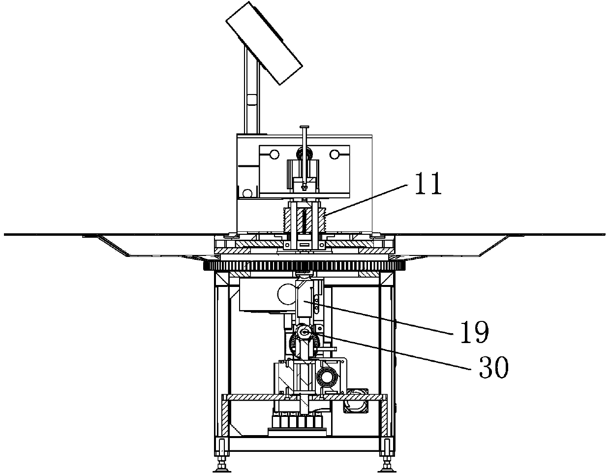
[0032] Such as figure 1 As shown in -6, the pipe bending machine of the present invention includes: a cabinet 1, a frame 2, pipe fittings 3, a console 4, a guide rail 5, a screw 6, a feeding clamp 7, a support 8, a clamping mechanism 9, and a pipe bending shaft 10, pipe bending wheel 11, cylinder 12, bar 13, supporting plate 14, turntable 15, large gear 16, pinion 17, servo motor 1 18, transmission shaft 19, first universal joint 20, gearbox 21, Servo motor two 22, limit seat 23, eccentric positioning mechanism 24, disk one 25, annular boss one 26, fixed plate 27, hollow support 28, the second universal joint 30.

[0033] The upper part of the chassis 1 is provided with a frame 2, the upper part of the frame 2 is provided with a console 4, the left side of the frame 2 is fixed, and a guide rail 5 and a lead screw 6 are arranged in parallel, and a through hole for passing through the pipe fitting 3 is provided in the frame 2. The left end of the guide rail 5 and the lead screw...


PUM


Abstract

The invention relates to a pipe-bending machine. A push-to-convey device used for conveying a pipe is arranged on a machine frame; a pair of pipe-bending shafts are arranged on the left side of the push-to-convey device; a pipe-bending wheel which can rotate around each pipe-bending shaft is respectively arranged on the pipe-bending shaft; an arc groove matched with the pipe in diameter is formed in the peripheral surface of each pipe-bending wheel; a limit base is fixedly arranged on the right side of each pipe-bending shaft; two semicircular positioning grooves are formed in the front and back of the left side of each limit base and is used for respectively limiting the pair of pipe-bending shafts; a round disc I suitable for eccentric rotation is arranged below the pipe-bending shafts; when the round disc I eccentrically rotates, one of the pair of pipe-bending shafts serves as an axial center, and one pipe-bending wheel rotates around the other pipe-bending wheel, so that the pipe between the pair of pipe-bending wheels is bent.

Description

technical field [0001] The invention relates to a pipe bender, especially a pipe bender with a synchronous rotation on the working surface, which is used for bending and forming heat dissipation pipes for refrigerators, freezers, air conditioners and other electrical appliances, especially for producing more elbows and shorter overall lengths. Long or soft heat pipes. Background technique [0002] The structure of the existing pipe bending machine is: a pushing device for conveying pipe fittings is provided on a platform, and the pipe fittings are pushed to the pipe bending device on the platform along with the rail by using the pushing device. Bending into a serpentine tube of required size, however, during the bending process, manual assistance is required between the tube body and the platform, that is, during the bending process of the tube, the head of the tube needs to be manually operated to follow the bending direction Rotate, otherwise the bending cannot be complet...

Claims


Application Information

Patent Timeline
IPC IPC(8): B21D7/08B21D7/12
Inventor 汤强庆汤红庆
Owner 合肥盛邦电器有限公司
Why Eureka
Try Eureka