
A support structure that can realize cast-in-place support structure with less support for concrete box girder of elevated approach bridge without platform

A technology with support structure and no platform, which is applied in the direction of erecting/assembling bridges, bridges, bridge construction, etc. It can solve the problems of many structural measures, high risks, and complicated installation and dismantling, so as to reduce construction difficulty, low cost, and save steel Effect

Active Publication Date: 2016-02-10
CCCC SHEC FOURTH ENG +1
View PDF6 Cites 0 Cited by
  • Summary
  • Abstract
  • Description
  • Claims
  • Application Information

AI Technical Summary

Problems solved by technology

[0003] For the scaffolding in the whole hall, the disadvantages are: there are many construction measures, and the installation and disassembly are more complicated; the requirements for the foundation are higher, and the bearing capacity and deformation of the bearing layer of the foundation and the weak underlying layer need to be checked and checked to ensure that they are within the allowable design. Within the range, and for the foundation range where scaffolding pipes are to be erected for the entire bridge span, the bearing capacity and deformation of the foundation must meet the requirements; the rigidity of a single scaffolding pipe is low, and for a bridge with a large clearance (greater than 8m) There is a great risk in the installation and dismantling of bridges and supports
[0004] For the cast-in-place construction of box girders without caps under the pier columns of land approach bridges with high clearance under the bridge, especially in the case of poor geological conditions, traditional support construction is used. From the perspective of safety and economy, have very large limitations

Method used


Image

  • A support structure that can realize cast-in-place support structure with less support for concrete box girder of elevated approach bridge without platform
  • A support structure that can realize cast-in-place support structure with less support for concrete box girder of elevated approach bridge without platform
  • A support structure that can realize cast-in-place support structure with less support for concrete box girder of elevated approach bridge without platform

Examples


Embodiment Construction

[0052] The following non-limiting examples illustrate the invention.

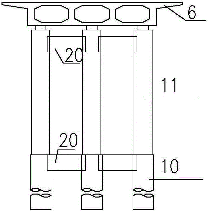
[0053] Such as Figures 1 to 22 As shown, a support structure that can realize the cast-in-place support structure of the concrete box girder of the elevated approach bridge without caps (such as figure 2 , 3 As shown, taking the elevated approach bridge with a span of 28m and a clear space under the bridge of 18m as an example), such as Figure 4 , 5 , 6, including supports for box girder cast-in-situ construction, box girder 6 is supported by cast-in-situ piles 10 and pier body 11 directly supported on it, and supports include horizontal joints 13 between rows arranged at the middle span of box girder 6 The two rows of connected middle columns 7 are symmetrically arranged in pairs on the side span columns 8 on both sides of each pier body 11, such as Figure 4 As shown, the side-span columns 8 are symmetrically arranged on both sides of the pier body 11. The trusses 15 and their connecting braces 16 ...


PUM


Abstract

The invention discloses a support structure for realizing no-cushion cap approach viaduct concrete box girder less-support cast-in-place, which belongs to the field of bridge superstructure construction, and comprises a support for box girder cast-in-place construction, wherein the box girder is supported by a cast-in-place pile and pier bodies directly supported thereon. The support structure is characterized in that the support comprises at least two rows of intermediate columns arranged in the middle of the box girder and connected in parallel, sidespan stand columns symmetrically arranged on two sides of each pier body in pairs, a truss located under the box girder and supported by the intermediate columns and the sidespan stand columns, and a connecting support thereof; each pair of sidespan stand columns is respectively supported by a hoop structure; each hoop structure is supported by the cast-in-place pile and surrounded and fixed on the pier bodies thereon; and stand columns on the same sides of the same row of pier bodies are connected through a parallel connected part in the middle, a lower cross beam on the top part and an outrigger on the bottom part. The support structure is applied to box girder cast-in-place of land approach bridge pier columns with higher clearance and without a cushion cap under the bridge, and is quick in construction progress, and low in engineering construction cost.

Description

technical field [0001] The invention belongs to the field of bridge superstructure construction, and is suitable for the cast-in-place construction of box girders without caps under the pier columns of overland viaducts under soft soil foundation environment. Background technique [0002] Bracket construction refers to the construction of installing formwork on the bracket, binding the steel skeleton, and pouring concrete on site. Because its construction is relatively simple, its cost is relatively low, and it is very suitable for monolithic structures, it is widely used in bridge construction, especially in the construction of urban overpasses and viaducts. At present, the most commonly used structural forms of traditional supports are scaffolding (such as figure 1 ), that is, by using corrugated beams, columns, connectors and other components, by controlling the spacing and step distance of steel pipe scaffolding poles, setting scissor braces and other structural measure...

Claims


Application Information

Patent Timeline
Patent Type & Authority Patents(China)
IPC IPC(8): E01D21/00E01D2/04
Inventor 郭佳嘉方顶李峰杨长虹李桂华
Owner CCCC SHEC FOURTH ENG
Learn More