Intercooler condensate to sump or positive crankcase ventilation flow

A technology for crankcase ventilation and condensate, which is applied in the direction of crankcase ventilation, machine/engine, engine lubrication, etc. It can solve problems such as unstable combustion, not allowing condensate to fully vaporize, and misfires

Active Publication Date: 2014-06-11
FORD GLOBAL TECH LLC
View PDF3 Cites 5 Cited by
  • Summary
  • Abstract
  • Description
  • Claims
  • Application Information

AI Technical Summary

Problems solved by technology

However, this method may not allow the condensate to fully vaporize before entering the engine
Therefore, liquid condensate entering the engine can cause combustion instability and misfire

Method used


Image

  • Intercooler condensate to sump or positive crankcase ventilation flow
  • Intercooler condensate to sump or positive crankcase ventilation flow
  • Intercooler condensate to sump or positive crankcase ventilation flow

Examples


Embodiment Construction

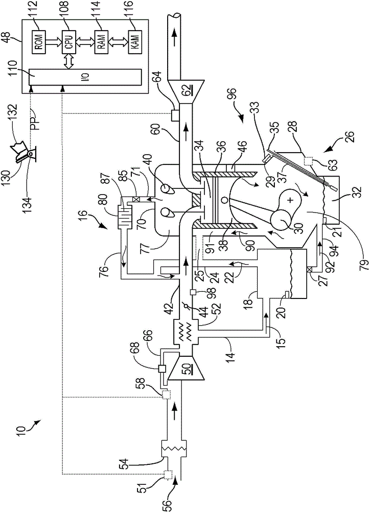
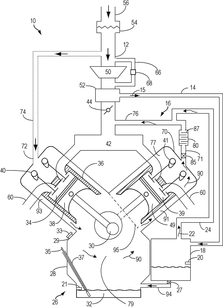
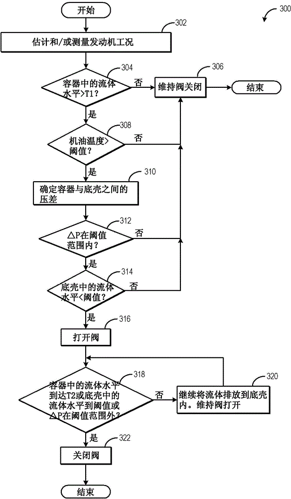
[0022] The following descriptions relate to methods for draining condensate from the charge air cooler (CAC) and introducing condensate into an engine system such as Figure 1-2 Systems and methods for at least one of forced crankcase ventilation flow and an engine oil sump for the engine system shown in . Liquid condensate can be drained into a liquid storage container where some of the liquid can evaporate into water vapor. Water vapor can leave the liquid storage container and enter the forced crankcase ventilation flow. Liquid condensate stored in a container can be drained into the engine sump for vaporization and removal. A drain valve in the fluid storage container controls the flow of liquid condensate into the engine oil sump. exist image 3 An example method of adjusting a drain valve in response to a fluid storage container and engine oil sump condition is described at . exist Figure 4 Example bleed valve adjustments in response to these conditions are shown at...


PUM


Abstract

Methods and systems are provided for removing condensate from a charge air cooler. Condensate may be drained from the charge air cooler and introduced into a positive crankcase ventilation flow or an engine oil sump. Introducing condensate into the engine oil sump may be controlled based on conditions of the engine oil sump and stored condensate.

Description

technical field [0001] The present invention relates to intercooler condensate for sump or forced crankcase ventilation flow. Background technique [0002] Turbocharged and supercharged engines can be configured to compress ambient air entering the engine in order to increase power. Compression of air can cause an increase in air temperature, so an intercooler or charge air cooler (CAC) can be used to cool the heated air, thereby increasing the density of the air and further increasing the potential power of the engine. Condensation can form in the CAC when the ambient air temperature drops, or during wet or rainy weather conditions, where the charge air is cooled below the dew point of the water. Condensate can collect at the bottom of the CAC or in the inner channels and cooling spoilers. When torque is increased, such as during acceleration, the increased mass air flow can strip condensate from the CAC, drawing it into the engine and increasing the likelihood of engine ...

Claims


Application Information

Patent Timeline
Patent Type & Authority Applications(China)
IPC IPC(8): F02B29/04F01M11/00F01M13/00
CPCF02B29/0468F01M13/028Y02T10/12F01M13/00
Inventor T·G·利昂M·D·切卡拉
Owner FORD GLOBAL TECH LLC
Why Eureka
Try Eureka