Vaporizing burner

A burner and evaporative technology, applied in the direction of burner, combustion type, combustion method, etc., can solve the problems of fuel retention, increase in manufacturing cost, increase in number of parts, etc., and achieve ignition, combustion, and stabilization Effect

Inactive Publication Date: 2019-07-19
SANGO CO LTD
View PDF6 Cites 0 Cited by
  • Summary
  • Abstract
  • Description
  • Claims
  • Application Information

AI Technical Summary

Problems solved by technology

[0008] However, providing a new fuel dispensing mechanism for uniformly spreading the fuel over the entire oil wick as described above may lead to problems such as a complicated structure of the evaporative burner, an increase in the number of parts, and an increase in manufacturing cost. sex
In addition, when the supply amount of fuel is small, the fuel cannot spread throughout the fuel distribution tank (the fuel distribution tank is not filled with fuel), and the fuel may stagnate below the fuel distribution mechanism.
As a result, there is a possibility that it may become difficult to spread the fuel evenly throughout the entire wick and to achieve early ignition of the fuel and stabilization of combustion.

Method used


Image

  • Vaporizing burner
  • Vaporizing burner
  • Vaporizing burner

Examples


no. 1 approach 》

[0057] Hereinafter, an example of the configuration of the evaporative burner (hereinafter, may be referred to as "the first burner") according to the first embodiment of the present invention will be described in more detail with reference to the drawings.

[0058]

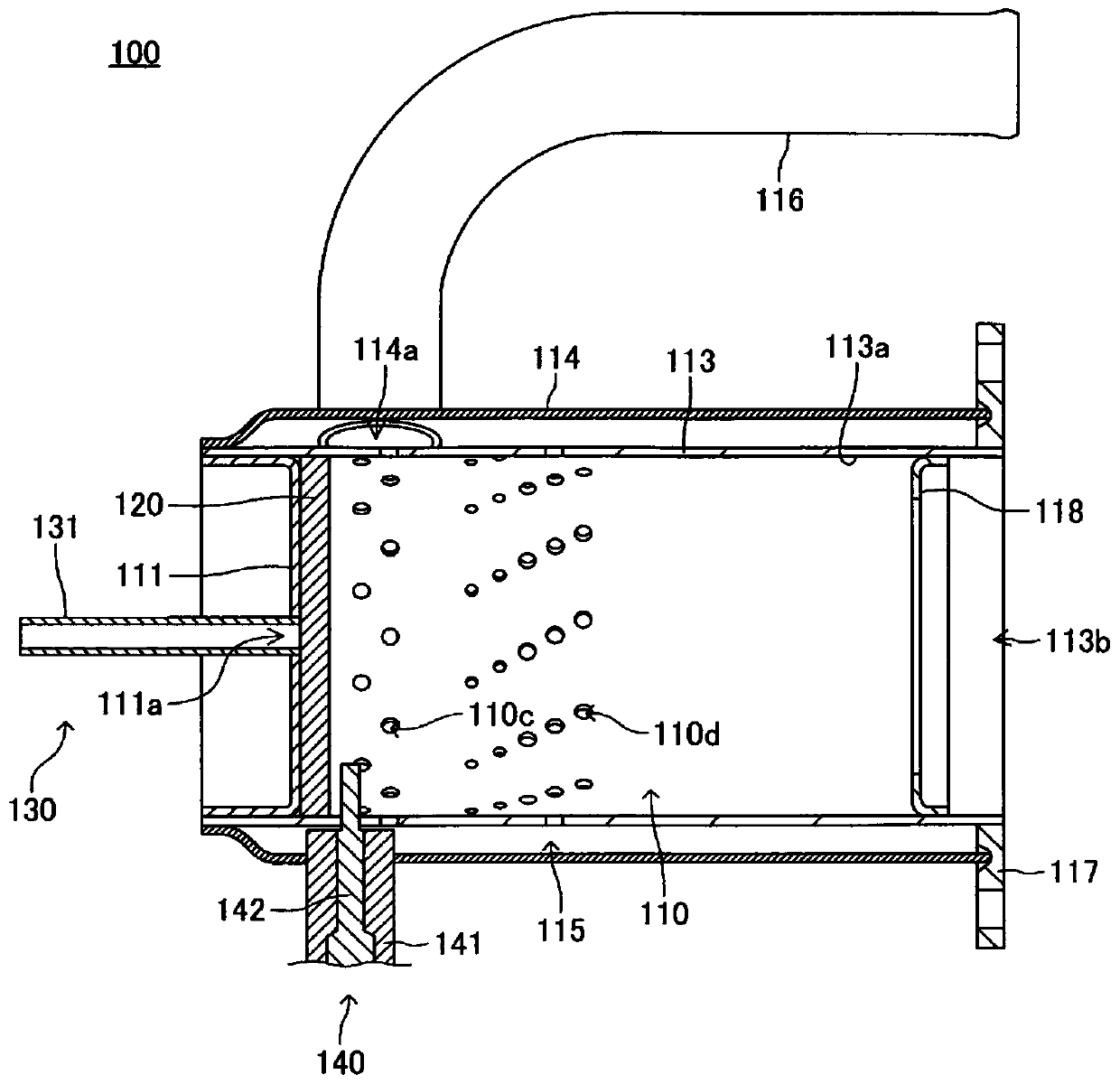
[0059] figure 1 It is a schematic cross-sectional view of the first combustor cut along a plane including the axis of the inner casing that defines the combustion chamber. In the following description, the upper side in the vertical direction ( figure 1 The upper side of the sheet) is referred to as "upper", and the opposite side, that is, the lower side, is referred to as "lower". And, towards figure 1 In the paper of , the left side (the impregnated member side) is referred to as the "upstream side", and the opposite side, that is, the right side is referred to as the "downstream side".

[0060] The first burner is an evaporative burner including a combustion chamber, an impregnated member, a fuel supply u...

no. 2 approach 》

[0125] Hereinafter, an example of the configuration of an evaporative burner (hereinafter, may be referred to as a "second burner") according to a second embodiment of the present invention will be described in more detail with reference to the drawings.

[0126]

[0127] The basic composition of the second burner is the same as the reference except for the points explained below. figure 1 The above described first burner 100 is the same. Therefore, description of the basic configuration of the second burner is omitted here.

[0128]

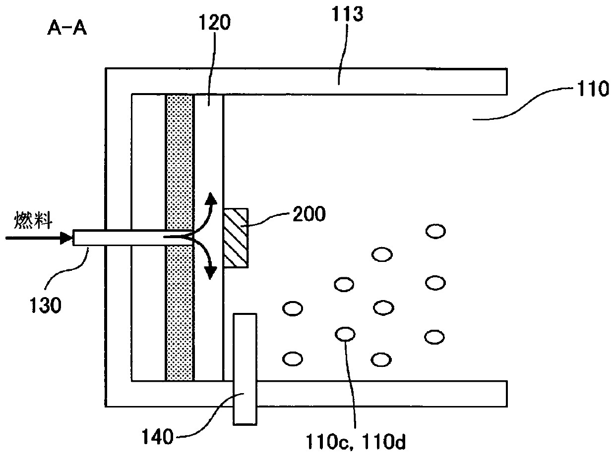
[0129] In the description of the first burner 100, as described above, the seepage preventing member 200 included in the burner of the present invention may be entirely embedded in the impregnated member, or may be entirely buried. It may be arranged outside the impregnated member, or part of it may be buried inside the impregnated member and the other part may protrude from the surface of the impregnated member.

[0130] The anti-seepage ...

no. 3 approach 》

[0135] Hereinafter, an example of the configuration of an evaporative burner (hereinafter, may be referred to as a "third burner") according to a third embodiment of the present invention will be described in more detail with reference to the drawings.

[0136]

[0137] The basic configuration of the third burner is the same as that of the above-mentioned first burner 100 and the second burner except that a partition member is further provided. Therefore, the structure of the third combustor will be described below focusing on the partition member. Thus, in Figure 10 in, with figure 1 Similarly, although the seepage prevention member 200 provided in the third burner 103 is omitted, the third burner 103 can have the seepage prevention member 200 and the rear burner that can be provided in the first burner 100 and the second burner described above. Various seepage prevention members 200 represented by the seepage prevention member 200 that can be provided in the modified ex...


PUM


Abstract

A vaporizing burner (100), wherein a seeping prevention member (200), which is a member having a lower rate of fuel permeation than an impregnated member (wick) (120), the rate of fuel permeation being a property value corresponding to the rate of permeation of fuel, is disposed in a facing region, which is a surface region of the impregnated member that faces, across the impregnated member, an impregnation region that is a surface region of the impregnated member through which fuel supplied at least from a fuel supply section (130) passes into the impregnated member. Due to this configuration, fuel supplied to the impregnated member from the fuel supply section can be uniformly distributed in the interior of the impregnated member, and fuel ignition and steady combustion can be achieved at an earlier stage. Preferably, a part of the seeping prevention member is embedded in the interior of the impregnated member, and the other part protrudes out from the surface of the impregnated member. More preferably, the seeping prevention member is configured as a part of a partition member that is disposed further downstream than the impregnated member in a combustion chamber (110).

Description

technical field [0001] This invention relates to evaporative burners. More specifically, the present invention relates to an evaporative burner capable of early ignition of fuel and stabilization of combustion. Background technique [0002] For example, harmful substances such as fine particles of coal (PM) and nitrogen oxides (NOx) are contained in exhaust gas discharged from an internal combustion engine such as a diesel engine. Therefore, from the viewpoint of global environmental protection, etc., exhaust purification mechanisms such as a PM-collecting filter (DPF) and a NOx reduction catalyst are widely implemented in the exhaust passage of an internal combustion engine to remove PM and NOx, thereby realizing exhaust gas. purification technology. [0003] However, since PM is continuously deposited in the DPF accompanying the operation of the internal combustion engine, it is necessary to burn the deposited PM at a predetermined time to regenerate the DPF. In additio...

Claims


Application Information

Patent Timeline
Patent Type & Authority Applications(China)
IPC IPC(8): F23D3/40
CPCF23D3/40B01B1/005F23Q7/08F23L1/00
Inventor 杉原申也土屋由弘
Owner SANGO CO LTD
Why Eureka
Try Eureka