Systems and methods for LP-EGR delivery in a variable displacement engine

A technology of LP-EGR and engine, which is applied in the direction of combustion engine, engine control, machine/engine, etc., and can solve the problems of increasing combustion instability and misfire

Active Publication Date: 2016-06-01
FORD GLOBAL TECH LLC
View PDF9 Cites 0 Cited by
  • Summary
  • Abstract
  • Description
  • Claims
  • Application Information

AI Technical Summary

Problems solved by technology

As a result, the engine may be exposed to higher EGR levels than the engine can withstand in non-VDE mode, resulting in increased combustion instability and misfire

Method used


Image

  • Systems and methods for LP-EGR delivery in a variable displacement engine
  • Systems and methods for LP-EGR delivery in a variable displacement engine
  • Systems and methods for LP-EGR delivery in a variable displacement engine

Examples


Embodiment Construction

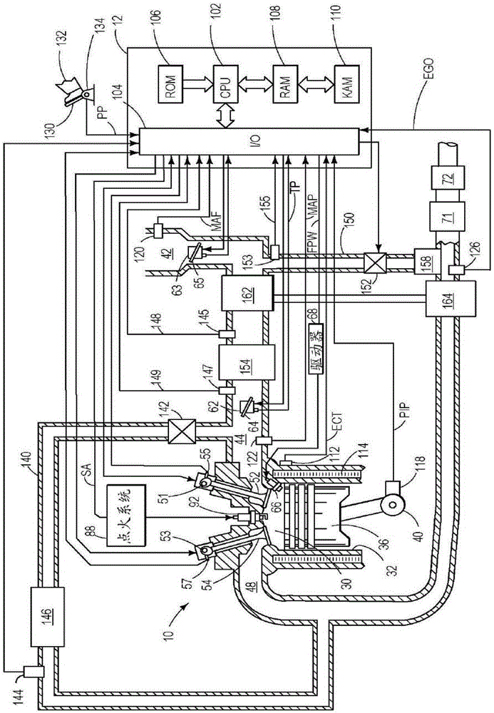
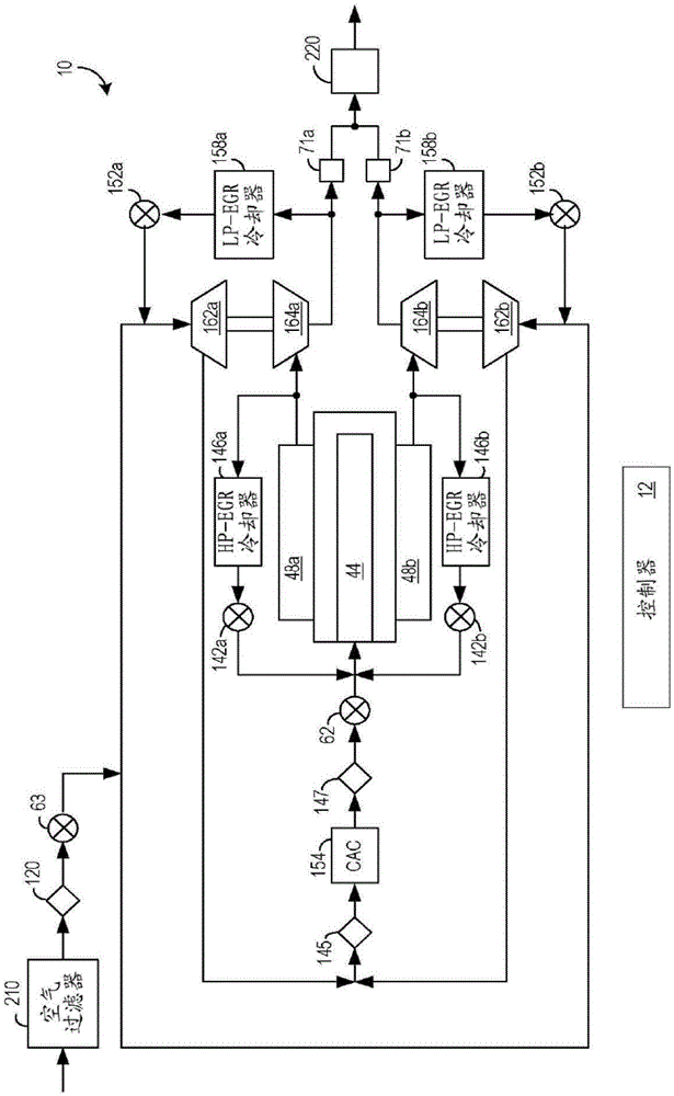
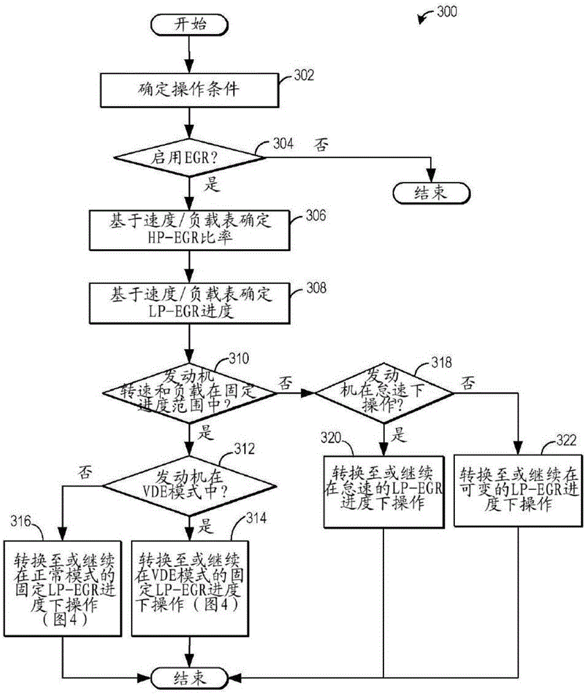
[0017] The present description relates to an EGR system connected to a turbocharged variable displacement engine in a motor vehicle. In one non-limiting example, a VDE engine may be configured to figure 1 A portion of an engine system shown in , wherein the engine includes at least one cylinder, a control system, a turbocharger, an exhaust gas recirculation system, and other components. The engine is also configured to have as in figure 2 Multiple cylinder banks shown in . The engine controller may be configured to execute control programs such as Figure 3 to Figure 4 Exemplary routine) to adjust LP based on the minimum cylinder load requirement of the engine when the engine transitions between operation with all cylinders enabled (non-VDE mode) and operation with one or more cylinders deactivated (VDE mode) - EGR schedule (schedule). Different EGR schedules may be selected based on engine speed load maps, such as the speed load maps of FIGS. 5A and 5B . refer to Imag...


PUM


Abstract

Methods and systems are provided for controlling LP-EGR flow in a variable displacement engine. In one example, a method may include providing a higher fixed LP-EGR percentage relative to a total intake air flow during a VDE mode, and providing a lower fixed EGR percentage relative to the total intake air flow during a non-VDE mode. Further, during a tip-out when operating in the VDE mode at a load below a threshold, transitioning out of the VDE mode after transitioning the LP-EGR from the higher fixed percentage to the lower fixed percentage.

Description

technical field [0001] The present description generally relates to methods and systems for improving LP-EGR delivery in variable displacement engines. Background technique [0002] Exhaust gas recirculation (EGR) systems recirculate a portion of exhaust gas from an engine exhaust to the engine intake system to improve fuel economy and vehicle emissions by reducing throttling losses and combustion temperatures. In a turbocharged engine, the EGR system may include a low pressure EGR (LP-EGR) circuit that diverts exhaust gas from downstream of the turbine of the turbocharger and injects the gas before the compressor. However, the LP-EGR loop has a long delivery delay because the exhaust gases must travel through the turbocharger compressor, high pressure air induction line, charge air cooler, and intake manifold before reaching the combustion chamber. Therefore, it is difficult to provide the desired amount of EGR to the cylinder, especially during transient conditions. [0...

Claims


Application Information

Patent Timeline
Patent Type & Authority Applications(China)
IPC IPC(8): F02D21/08
CPCF02D21/08F02D41/107F02D41/005F02D15/00F02D17/02F02D41/0087F02D41/0065Y02T10/40
Inventor 戈皮昌德拉·苏尼拉詹姆斯·艾尔佛雷德·希尔迪奇克里斯·保罗·格卢格拉林恩·艾梅·切斯尼丹尼尔·约瑟夫·斯泰尔斯
Owner FORD GLOBAL TECH LLC
Why Eureka
Try Eureka