chain drive mechanism

A transmission mechanism and chain-type technology, applied in the direction of transmission devices, belts/chains/gears, mechanical equipment, etc., can solve the problems of excessively increased frictional resistance, increased contact area, large load, etc., to reduce contact frictional resistance and improve smoothness sex, avoiding the effect of smooth sex

Inactive Publication Date: 2016-10-19
SANJET INT
View PDF5 Cites 0 Cited by
  • Summary
  • Abstract
  • Description
  • Claims
  • Application Information

AI Technical Summary

Problems solved by technology

[0005] 2. Based on the first point above, the flat second part of each sliding assembly must go deeper into the gap between the upper and lower clamping plates to obtain more clamping area to improve clamping stability. In this way, due to the increase of the contact area between the second part and the upper and lower splints, the frictional resistance is increased, which is not conducive to the smooth movement of the sliding assembly.
Therefore, the power source (motor) that drives the chain to rotate will be overloaded

Method used


Image

  • chain drive mechanism
  • chain drive mechanism
  • chain drive mechanism

Examples


Embodiment Construction

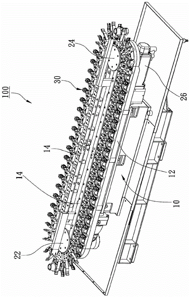
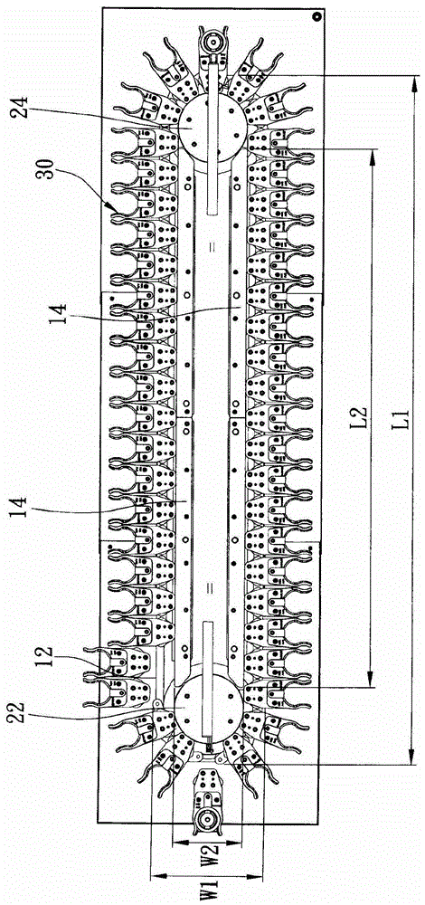
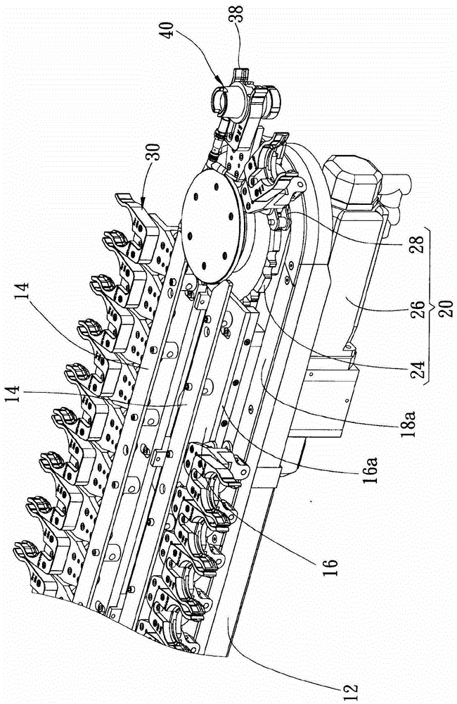
[0036] The chain transmission mechanism provided by the present invention includes a machine table, a transmission unit and a plurality of moving units. Wherein the machine table has a track, and the track defines a first constraint surface and a second constraint surface; the transmission unit has a chain looped in the track of the machine table, and the chain can be driven to follow the track rotation; the moving units are arranged along the track of the machine table, and move synchronously with the rotation of the chain, each of the moving units has a first rolling element and a second rolling element, wherein the first rolling element contacts the The first constraining surface does not contact the second constraining surface, and the second rolling element contacts the second constraining surface but does not contact the first constraining surface.

[0037] Therefore, the rolling contact is used to reduce the frictional resistance, thereby improving the smooth operation ...


PUM


Abstract

A chain transmission mechanism includes a machine table, a transmission unit and a plurality of moving units. Wherein the machine table has a track, and the track defines a first constraint surface and a second constraint surface; the transmission unit has a chain wound around the track; the moving units are arranged in the track, and are controlled by the chain To drive displacement, each moving unit has a first rolling member that contacts the first constraining surface but does not contact the second constraining surface, and has a second rolling member that contacts the second constraining surface but does not contact the first constraining surface . Therefore, during the displacement process of these mobile units, the contact frictional resistance can be reduced. At the same time, the positions of the first and second rolling elements are arranged up and down, front and back, which can resist the problem of one side of the mobile unit being biased, so as to improve the operation of the mechanism. smoothness.

Description

technical field [0001] The present invention is related to the transmission structure, and more specifically refers to a chain-type transmission mechanism. Background technique [0002] It is known that the chain-type transmission mechanism is often used in automatic tools, such as a comprehensive cutting machine with an automatic tool change mechanism, the purpose is to accommodate a large number of tools, and to provide stable support and conduction when performing the automatic tool change function . In China Taiwan Announcement No. I 331065 "Orbital Tool Magazine Structure" invention patent case, it discloses a technology that utilizes chains to drive cutting tools. In the case that the movement of the tool holder is not smooth due to the swaying of the chain, the specific technical means adopted is to set an upper and lower clamping plate in a manner to maintain a small distance, and a ring-shaped rail groove is recessed on the bottom surface of the upper clamping plat...

Claims


Application Information

Patent Timeline
Patent Type & Authority Patents(China)
IPC IPC(8): F16H7/06F16H7/18B23Q3/155
CPCB23Q3/1554B23Q3/15553B23Q2003/15527B23Q3/15724
Inventor 张庆三
Owner SANJET INT
Why Eureka
Try Eureka