Environment-friendly heat treatment system

A heat treatment system, an environmentally friendly technology, applied in lighting and heating equipment, combustion methods, combustion types, etc., can solve the problems of energy consumption, non-environmental protection, uneven heating of waste, and lack of waste

Inactive Publication Date: 2014-06-11
宝晶环境科技(合肥)有限公司
View PDF11 Cites 3 Cited by
  • Summary
  • Abstract
  • Description
  • Claims
  • Application Information

AI Technical Summary

Problems solved by technology

[0003] However, the current incineration or heat treatment is generally aimed at soil or industrial waste treatment respectively, and has specific design, and it is not easy to be flexible and consistent with heat treatment conditions for different waste requirements, which has unsatisfactory applicability.
[0004] In addition, the incinerator and melting furnace are mainly equipped with a burner and heated by the burner, but it is still easy to cause uneven heating of the waste in the center of the furnace, resulting in ineffective incineration and loss of thermally decomposed toxic substances, and the heating unit must be continuously replenished Fuel oil, electricity or other energy sources generate heating energy, which has the disadvantage of energy consumption and environmental protection
[0005] In view of this, the designer aimed at the many shortcomings and inconveniences caused by the imperfect design of the above-mentioned environmental protection treatment system, and deeply conceived, and actively researched and improved the trial to develop and design this case

Method used


Image

  • Environment-friendly heat treatment system
  • Environment-friendly heat treatment system
  • Environment-friendly heat treatment system

Examples


Embodiment Construction

[0045] In order to further explain the technical solution of the present invention, the present invention will be described in detail below through specific embodiments.

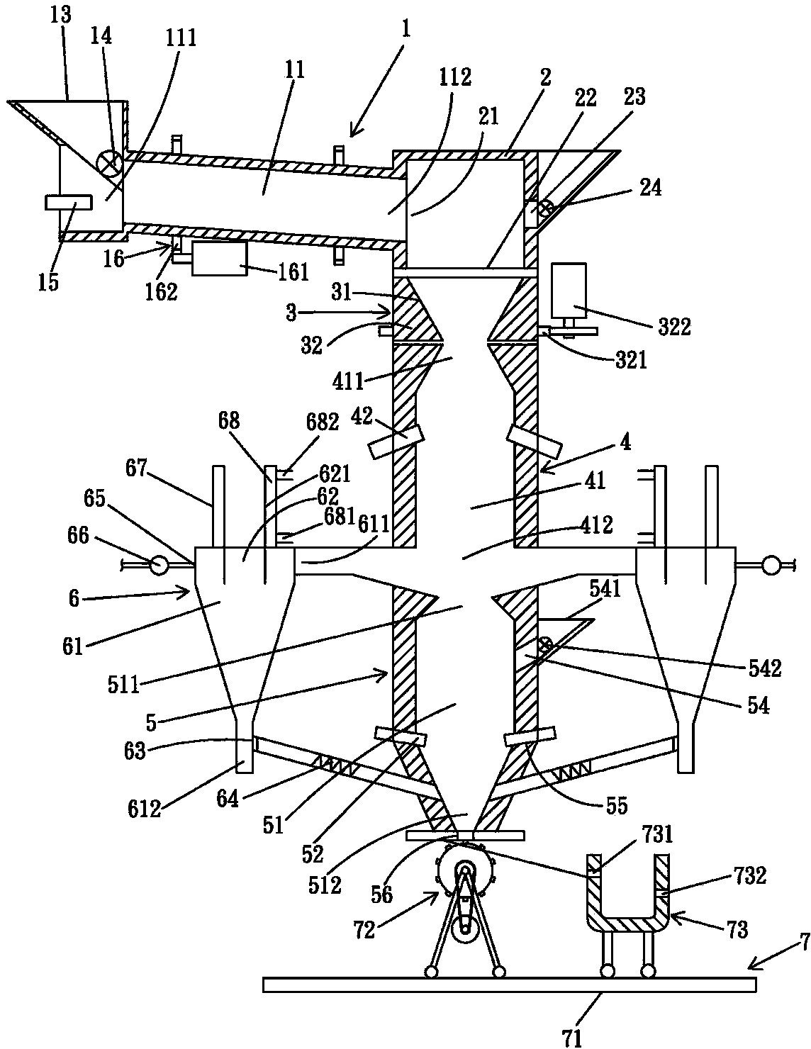
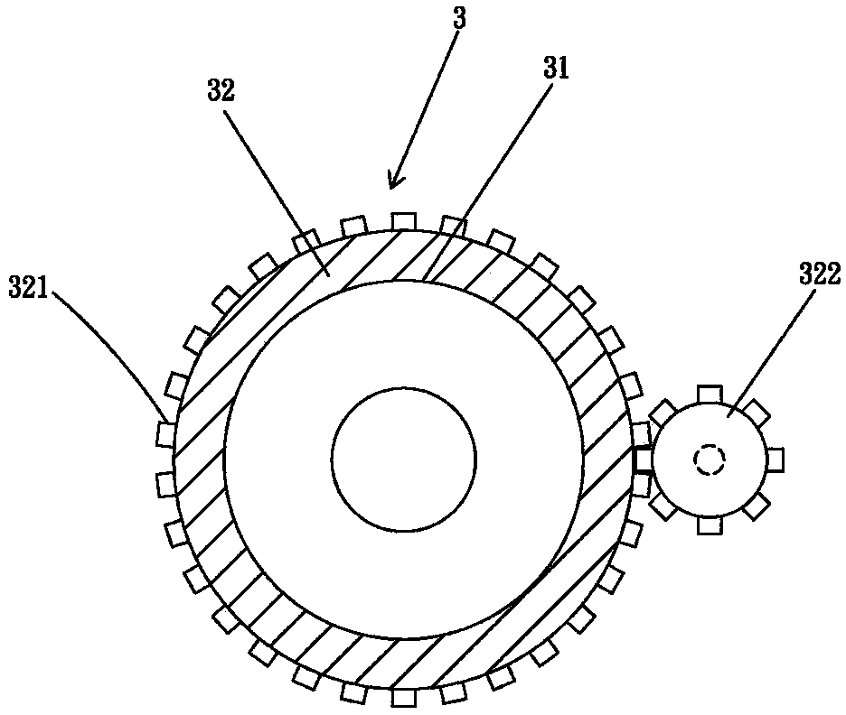
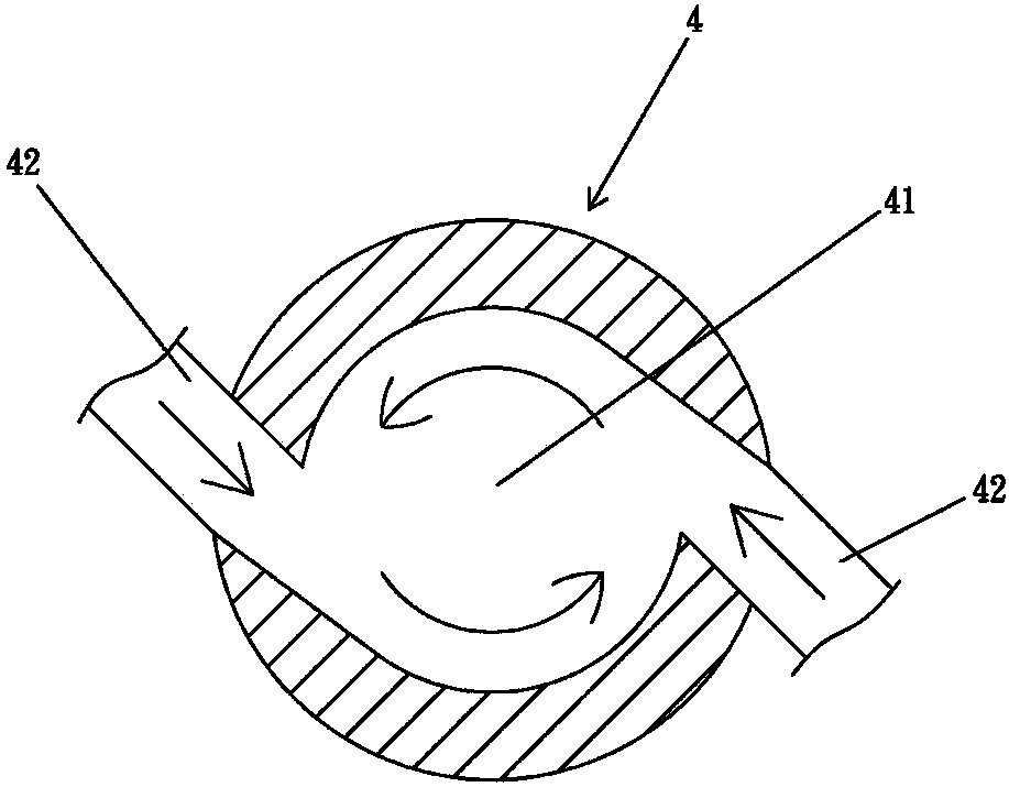
[0046] See Figure 1 to Figure 3 , The present invention includes a first heating furnace 1, a buffer chamber 2, a sprinkling device 3, a second heating furnace 4, a third heating furnace 5, at least one dust collecting device 6, a collecting device 7 , The first heating furnace 1 has a first heating chamber 11, the first heating chamber 11 has an inlet 111, an outlet 112, and a hopper 13 and a feeder 14 are connected to the inlet 111 to provide quantitative feeding. A heating chamber 11 is provided with a heater 15, and the first heating furnace 1 is connected to a rotating device 16. The rotating device 16 has a power motor 161 and a gear 162 to provide the first heating furnace 1 rotating action, which can provide general incineration operations or soil 81 dry preheating, and its heating temperature can be ...


PUM


Abstract

The invention discloses an environment-friendly heat treatment system. The environment-friendly heat treatment system comprises a first time heating furnace, a buffer chamber, a sprinkling device, a second time heating furnace, a third time heating furnace and at least one dust collection device; the first time heating furnace comprises a first heating chamber which is provided with a heater; the buffer chamber is connected with the first heating chamber which can provide for a flue gas velocity buffer; the sprinkling device comprises a funnel-shaped sprinkling plate which is connected with the buffer chamber and arranged on a rotating base; the second time heating furnace comprises a second heating chamber which is connected with the sprinkling plate and a heater; the third time heating furnace comprises a third heating chamber which is arranged under the second heating chamber and connected with a heater; the dust collection device comprises a dust collection chamber which comprises an inlet, an outlet and a smoke outlet; the inlet is connected between the second heating chamber and the third heating chamber; the outlet of the dust collection chamber is connected under the third heating chamber and provided with a direction valve and a conveyor. According to the environment-friendly heat treatment system, the applicability is good and the consistent efficient environment-friendly treatment can be achieved.

Description

Technical field [0001] The present invention relates to an environmentally friendly heat treatment system, in particular to an environmentally friendly heat treatment system that is suitable for contaminated soil or medical industry or other waste treatment with better applicability, consistency and efficient energy saving. Background technique [0002] In the modern, industrially developed industry, various industrial products are manufactured one after another. Therefore, when the manufacturing process is lost or the finished product is damaged after a period of use, various industrial wastes and sludge will be produced, and food will be produced in human life. , Medical or other various wastes, the current treatment method is generally placed in an incinerator or melting furnace to form fly ash slag or molten block burning treatment. [0003] However, the current incineration or heat treatment generally has specific designs for soil or industrial waste treatment, and it is not e...

Claims


Application Information

Patent Timeline
Patent Type & Authority Applications(China)
IPC IPC(8): F23G7/00
Inventor 胡耀忠
Owner 宝晶环境科技(合肥)有限公司
Why Eureka
Try Eureka