Anti-drift thin roof ventilator

A ventilator, thin technology, used in ventilation systems, roof drainage, space heating and ventilation, etc., can solve problems such as floating rain, rain leakage, inconvenience in production, etc., to achieve strong wind resistance, avoid water leakage, Good anti-rain performance

Active Publication Date: 2016-07-06
JIANGSU YANGZHOU AIR CONDITIONING ENG
View PDF9 Cites 0 Cited by
  • Summary
  • Abstract
  • Description
  • Claims
  • Application Information

AI Technical Summary

Problems solved by technology

Existing roof ventilators generally have defects of rain leakage and floating rain in stormy weather, which brings inconvenience to production

Method used


Image

  • Anti-drift thin roof ventilator
  • Anti-drift thin roof ventilator

Examples


Embodiment Construction

[0020] Below in conjunction with accompanying drawing, the specific embodiment of the present invention is described in further detail:

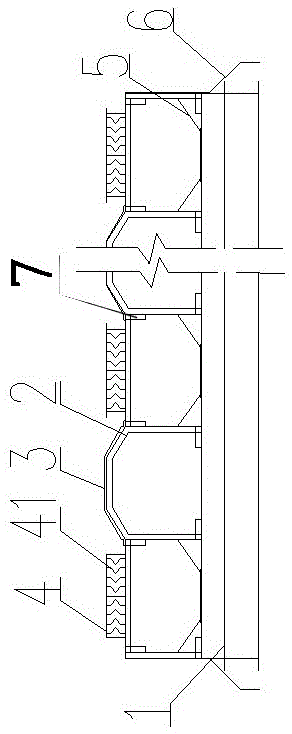
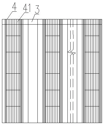
[0021] Such as Figure 1-2 As shown, the anti-drifting thin roof ventilator includes a ventilator base 1, a ventilator frame 2, a rain shield 3, a rain director 4, a thin plate 41, a sump 5, a flashing plate 6 and a notch 7. The ventilator framework 2 is angle steel or angle aluminum or square tube, and the rain shield is steel plate or aluminum alloy plate or daylighting plate. The ventilator base 1 is installed on the ventilator steel foundation on the truss of the factory building, and the herringbone ventilator skeleton 2 is installed on the ventilator base 1; the multi-row rain shield 3 and the multi-row rain director 4 are installed side by side at intervals On the ventilator frame 2, a notch 7 in the vertical direction is provided at the junction of the rain shield 3 and the rain director 4. The rain director 4 is composed of a plur...


PUM


Abstract

The invention relates to a rain floating prevention thin roof ventilator which comprises a ventilator base, a ventilator skeleton, a rain baffle and rain orientators. The ventilator base is arranged on a plant roof truss; the ventilator skeleton is fixedly arranged on the ventilator base; and the ventilator skeleton is provided with a plurality of lines of rain orientators and a plurality of lines of catch basins. The rain floating prevention thin roof ventilator is characterized in that each rain orientator is formed by horizontally arranging a plurality of thin plates at intervals; a broken line or curved line passage of which the slope increase and decrease are transformed for more than one time is formed between each two adjacent thin plates; and a lower opening of each passage correspondingly extends to the position above the corresponding catch basin below the corresponding rain orientator. After entering the passages of the rain orientators to be guided, rainwater vertically flows into the catch basins and can be effectively avoided floating into a plant.

Description

technical field [0001] The invention relates to the field of roof ventilators, in particular to a rainproof thin roof ventilator. Background technique [0002] Roof ventilators are generally used for ventilation of large factory buildings, and the hot air and smoke in the factory buildings are discharged from the workshop through the ventilators. Existing roof ventilators generally have defects of rain leakage and drifting rain during violent storms, which brings inconvenience to production. Contents of the invention [0003] In order to solve the deficiencies in the prior art, the object of the present invention is to provide an anti-drifting thin roof ventilator. [0004] The technical scheme that the present invention takes is: [0005] A thin-type roof ventilator for preventing drifting rain, comprising a ventilator base, a ventilator skeleton, a rain shield and a rain director, the ventilator base is installed on the frame of the factory building, and the ventilator...

Claims


Application Information

Patent Timeline
Patent Type & Authority Patents(China)
IPC IPC(8): F24F7/02E04D13/04
Inventor 肖一丹肖宏灿
Owner JIANGSU YANGZHOU AIR CONDITIONING ENG
Why Eureka
Try Eureka