A servo position control method applied to engraving and milling machine

A control method and technology of engraving and milling machine, applied in the field of servo control, can solve problems such as large position error

Active Publication Date: 2016-02-10
NANJING ESTUN AUTOMATION CO LTD
View PDF10 Cites 0 Cited by
  • Summary
  • Abstract
  • Description
  • Claims
  • Application Information

AI Technical Summary

Problems solved by technology

[0005] The invention discloses a servo position control method applied to an engraving and milling machine, which solves the problem that the position error of the X axis, Y axis and Z axis of the engraving and milling machine at the commutation point is relatively large when the existing control method is applied to the engraving and milling machine. big problem

Method used


Image

  • A servo position control method applied to engraving and milling machine
  • A servo position control method applied to engraving and milling machine
  • A servo position control method applied to engraving and milling machine

Examples


Embodiment Construction

[0024] The present invention will be described in further detail below in conjunction with the accompanying drawings and specific embodiments.

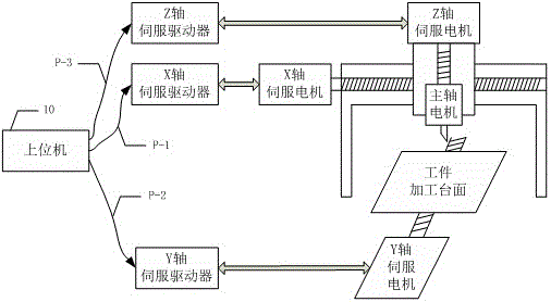
[0025] figure 1 It is a schematic diagram of the structure of the engraving and milling machine. The upper computer 10 outputs three position signals P-1, P-2 and P-3, which are respectively sent to the X-axis, Y-axis and Z-axis servo drivers in the form of pulses, and the X-axis and Y-axis and Z-axis servo drivers drive X-axis, Y-axis and Z-axis servo motors respectively. The Y-axis servo motor drives the workpiece processing table to move in the Y-axis direction; the Z-axis servo motor drives the spindle motor to move in the Z-axis direction, and the spindle motor drives the tool to rotate at high speed, responsible for engraving and milling the workpiece; the Z-axis servo motor and the spindle motor are integrated Driven by the X-axis servo motor, it moves in the X-axis direction.

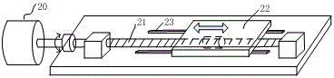
[0026] figure 2 It is a schematic diagram of ...


PUM


Abstract

The invention discloses a servo position control method applied to an engraving and milling machine. In the method, speed feed-forward and current feed-forward are introduced, an output signal of a position controller is added to a feed-forward speed signal output by a feed-forward controller, a speed signal fed back by a servo motor is subtracted from the sum to get an input signal of a speed controller, a position pulse signal sent by an upper computer is subjected to differential treatment by a feed-forward controller to obtain a feed-forward speed signal, an output signal of the speed controller is added to a current feed-forward signal output by the feed-forward controller, and a current signal fed back by the servo motor is subtracted from the sum to get an input signal of a current controller, wherein the current feed-forward signal is got after an acceleration current signal is added to a friction current signal. Current feed-forward plays a role in improving servo speed response, and speed feed-forward plays a role in improving servo position response. By means of the method, phase change point position errors of the X-axis, Y-axis and Z-axis of the engraving and milling machine are reduced, and workpiece machining precision and efficiency are improved.

Description

technical field [0001] The invention relates to a servo position control method applied to engraving and milling machines, in particular to a servo position control method applied to engraving and milling machines with speed feedforward and current feedforward, and belongs to the technical field of servo control. Background technique [0002] The engraving and milling machine is a CNC machine tool that uses small tools, high power and high-speed spindle motors. It is characterized by both engraving and milling. It is widely used in occasions where precision molds are processed in one time. [0003] based on figure 1 and figure 2 , to illustrate the basic composition of the engraving and milling machine control system: the upper computer 10 is responsible for completing the trajectory planning required for workpiece processing, and the servo drivers of the X-axis, Y-axis and Z-axis work in position mode and are responsible for receiving the pulse commands sent by the upper ...

Claims


Application Information

Patent Timeline
Patent Type & Authority Patents(China)
IPC IPC(8): G05B19/19
Inventor 范中华扶文树齐丹丹吴波
Owner NANJING ESTUN AUTOMATION CO LTD
Why Eureka
Try Eureka