
Method for predicting vibration performance of movable guide vane of water turbine

A technology of movable guide vanes and vibration characteristics, applied in special data processing applications, instruments, electrical digital data processing, etc., can solve problems such as ignoring the influence of guide vanes, reducing simulation accuracy, and problem complexity

Inactive Publication Date: 2014-06-11
KUNMING UNIV OF SCI & TECH
View PDF3 Cites 14 Cited by
  • Summary
  • Abstract
  • Description
  • Claims
  • Application Information

AI Technical Summary

Problems solved by technology

However, due to the complexity of the problem, no satisfactory results have been obtained so far
[0003] However, there are some obvious deficiencies in the traditional blade vibration analysis method: for example, the traditional structural dynamics analysis method isolates the flow field from the deformation of the guide vane, ignores the influence of the deformation of the guide vane on the flow field, and introduces a large number of linearization Hypothesis, weakening or even eliminating nonlinearity, greatly reducing simulation accuracy
In the past, a single flow field calculation or a single structure calculation played a guiding role in unit efficiency, cavitation prediction, or structural design, but it was powerless to study hydraulic vibration, blade crack formation, etc., so the method of fluid-solid coupling calculation was adopted , it is imperative to study the coupled vibration between this type of complex turbulent flow and large thin-walled structures, and it is also one of the most challenging topics

Method used


Image

  • Method for predicting vibration performance of movable guide vane of water turbine
  • Method for predicting vibration performance of movable guide vane of water turbine
  • Method for predicting vibration performance of movable guide vane of water turbine

Examples


Embodiment approach 1

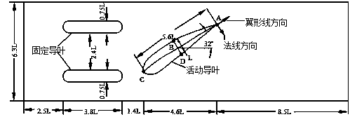
[0065] Embodiment 1: The following takes the fluid-solid coupling calculation model of movable guide vanes in the water guide mechanism of a certain type of Francis turbine as an example. For specific calculation objects, see image 3 , the present invention will be described in further detail.

[0066] Step 1: Calculation of the initial value of the steady-state flow field

[0067] Set the boundary conditions of the flow field, the left side is the velocity inlet boundary, the velocity =0.816m / s, the right side is the free flow, and the rest of the boundary adopts solid wall surface, the steady-state calculation of the surrounding flow field under the initial configuration of the guide vane is carried out, and the stress of the fluid side node of the coupling interface is extracted at the same time;

[0068] Step 2: Synchronous Bidirectional Iteration

[0069] By calling the synchronous bidirectional iteration module, the entire fluid-structure interaction system i...


PUM


Abstract

The invention relates to a method for predicting vibration performance of a movable guide vane of a water turbine and belongs to the technical field of hydraulic machines and system coupling simulation thereof. The method comprises the following steps: acquiring a steady flow field as the initial value condition of the flow field under the initial design configuration of the guide vane by utilizing design condition flow as the inlet boundary condition of fluid calculation; alternately calling a structural calculation module and a fluid calculation module in one time step, and integrally and synchronously advancing the fluid calculation and structural calculation after the condition of convergence is met; transmitting fluid-solid boundary information through an interface information switching module; outputting structural vibration displacement in time history. According to the method provided by the invention, coupling calculation of the guide vane and the flow field is realized; the method is obviously improved in accuracy in comparison with traditional simple structural dynamics methods and unidirectional coupling methods, and moreover, the whole vibration development process of the guide vane can be observed, and therefore, the structural design can be helped better guided, so that fluid-solid coupling goes into practical engineering application from theoretical study.

Description

technical field [0001] The invention relates to a method for predicting the vibration characteristics of movable guide vanes of a water turbine, and belongs to the technical field of hydraulic machinery and system coupling simulation thereof. Background technique [0002] The problem of unit vibration and blade cracks has become a key technical problem that needs to be solved urgently in hydropower stations. However, the mechanism of hydraulic vibration of hydraulic turbines is very complicated, with many difficulties and involves many disciplines, such as hydraulic disturbance caused by Karman vortices behind the blades, cavitation and shedding The hydroelastic vibration of the water and the vibration induced by the cavity vortex in the draft tube, etc. These are extremely difficult problems, and they are also the main reasons for the vibration of the turbine, which have been paid great attention by the academic and engineering circles for many years. However, due to the co...

Claims


Application Information

Patent Timeline
Patent Type & Authority Applications(China)
IPC IPC(8): G06F17/50
Inventor 王文全闫妍张立翔曾云李金海李泽杨锡阶郭涛
Owner KUNMING UNIV OF SCI & TECH
Learn More