Photovoltaic module lifting and rotating mechanism

A lifting and rotating, photovoltaic module technology, applied in the direction of photovoltaic power generation, electrical components, semiconductor devices, etc., can solve the problem of high labor intensity, achieve the effect of convenient operation, reduce labor intensity of employees, and simple structure

Active Publication Date: 2014-06-11
JUNFENG SOLAR ENERGY JIANGSU
View PDF3 Cites 2 Cited by
  • Summary
  • Abstract
  • Description
  • Claims
  • Application Information

AI Technical Summary

Problems solved by technology

If it is replaced by one person, this person needs to circle the table while cutting, and then circle the table while clearing the glue, which is labor-intensive

Method used


Image

  • Photovoltaic module lifting and rotating mechanism

Examples


Embodiment Construction

[0010] Specific embodiments of the present invention will be described in detail below in conjunction with the accompanying drawings.

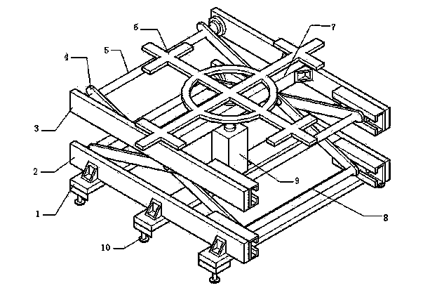
[0011] Such as figure 1 As shown, a photovoltaic module lifting and rotating mechanism includes a bottom plate 1, a side plate, a cross strut 4, a fixed shaft 5, a movable shaft 8 and a cylinder 9, the side plate includes a lower side plate 2 and an upper side plate 3, and the side plate One end is provided with a sliding groove, the lower side plate 2 is fixedly installed on the base plate 1, the cylinder 9 is installed in the center of the base plate 1, the fixed rotating shaft 5 is fixedly installed on one end of the side plate, and the movable rotating shaft 8 is movably socketed on the other end of the side plate. In the movable groove, one end of the cross strut 4 is socketed on the fixed rotating shaft 5, and the other end is socketed on the movable rotating shaft 8. The upper side plate 3 and the beam 7 form an I-shaped structure, and ...


PUM


Abstract

The invention discloses a photovoltaic module lifting and rotating mechanism which comprises an assembly line support and a transmission belt. The transmission belt is fixedly installed on the top of the assembly line support and the front end of the assembly line support is provided with a first infrared sensor. The rear end of the assembly line support is provided with a second infrared sensor. A base of the assembly line support is fixedly provided with a fan and a lifting mechanism. A roller fixing support is installed on the top of the assembly line support. A high-temperature-resisting roller is installed on the roller fixing support. The photovoltaic module lifting and rotating mechanism has the advantages of being simple in structure and convenient to operate. An assembly line unit can automatically lift a module when the module stays for a long time, so that the high-temperature assembly is separated from the transmission belt and at the same time, the fan below the module is started and cooling of the module is accelerated. Thus, the transmission belt is protected. Excessively rapid ageing of the transmission belt is prevented and equipment abrasion is relieved.

Description

technical field [0001] The invention relates to the photovoltaic module manufacturing industry, in particular to a photovoltaic module lifting and rotating mechanism. Background technique [0002] In the production process of photovoltaic modules, the operation method of glue removal and edge cutting is to put the modules on a fixed table, and two employees stand at both ends of the table to clean half of the modules respectively, and each person cuts a long side a short side. If it is replaced by one person, this person needs to circle the table while cutting, and then circle the table while clearing the glue, which is labor-intensive. Contents of the invention [0003] Purpose of the invention: The purpose of the invention is to provide a lifting and rotating mechanism for photovoltaic modules in order to solve the deficiencies of the prior art. [0004] Technical solution: A photovoltaic module lifting and rotating mechanism, including a bottom plate, a side plate, a ...

Claims


Application Information

Patent Timeline
Patent Type & Authority Applications(China)
IPC IPC(8): H01L31/18
CPCH01L31/1876Y02E10/50Y02P70/50
Inventor 刘锦峰
Owner JUNFENG SOLAR ENERGY JIANGSU
Why Eureka
Try Eureka