Uninterrupted rechargeable battery power supply

A rechargeable battery and power supply technology, which is applied in the field of uninterrupted rechargeable battery power supply, can solve the problems of high power requirements and unsatisfactory technology, and achieve the effect of high output voltage quality

Inactive Publication Date: 2014-06-11
XIAN SINENG NETWORK SCI & TECH
View PDF0 Cites 2 Cited by
  • Summary
  • Abstract
  • Description
  • Claims
  • Application Information

AI Technical Summary

Problems solved by technology

[0005] However, in some cases, the power supply needs to be completely isolated, and the power requirements are relatively large, and the disclosed technology cannot meet the technical requirements.

Method used


Image

  • Uninterrupted rechargeable battery power supply
  • Uninterrupted rechargeable battery power supply
  • Uninterrupted rechargeable battery power supply

Examples


Embodiment 1

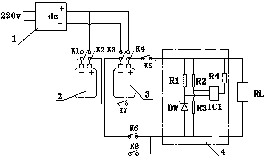
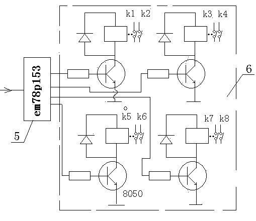
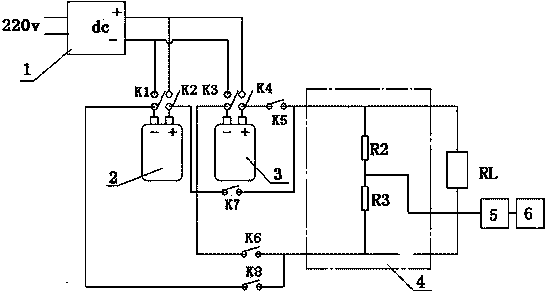
[0020] In the figure, 1. AC charging power supply; 2. First rechargeable battery; 3. Second rechargeable battery; 4. Voltage detection circuit; 5. Single-chip microcomputer; 6. Relay control circuit.

specific Embodiment approach

[0021] Example 1

[0022] Such as figure 1 and figure 2 As shown, an uninterrupted rechargeable battery power supply, the input terminal of the AC charging power supply 1 is electrically connected to the AC power supply, and a set of relays and two sets of switches (K1, K2) at the positive and negative output terminals of the AC charging power supply 1 are connected in series to the first rechargeable battery 2 The positive and negative power terminals of the AC charging power supply 1, the other set of relays and two sets of switches (K3, K4) are connected in series to the positive and negative power terminals of the second rechargeable battery 3; the positive and negative power terminals of the first rechargeable battery 2 Two sets of switches (K7, K8) are connected in series in the load RL loop through a relay, and the positive and negative power supply terminals of the second rechargeable battery 3 are also connected in series in the load RL loop through another relay se...

Embodiment 2

[0026] Such as image 3 As shown, an uninterrupted rechargeable battery power supply, the input terminal of the AC charging power supply 1 is electrically connected to the AC power supply, and a set of relays and two sets of switches (K1, K2) at the positive and negative output terminals of the AC charging power supply 1 are connected in series to the first rechargeable battery 2 The positive and negative power terminals of the AC charging power supply 1, the other set of relays and two sets of switches (K3, K4) are connected in series to the positive and negative power terminals of the second rechargeable battery 3; the positive and negative power terminals of the first rechargeable battery 2 Two sets of switches (K7, K8) are connected in series in the load RL loop through a relay, and the positive and negative power supply terminals of the second rechargeable battery 3 are also connected in series in the load RL loop through another relay set of switches (K5, K6). , there is...


PUM


Abstract

The invention relates to a power supply, especially to an uninterrupted rechargeable battery power supply. The uninterrupted rechargeable battery power supply includes an alternating-current charging power supply, a first rechargeable battery and a second rechargeable battery. The input end of the alternating-current charging power supply is electrically connected with an alternating-current power supply. Two sets of switches (K1, K2) of one set of relay at the positive and negative output ends of the alternating-current charging power supply are connected in series to the positive and negative power supply ends of the first rechargeable battery. Two sets of switches (K3, K4) of another set of relay at the positive and negative output ends of the alternating-current charging power supply are connected in series to the positive and negative power supply ends of the second rechargeable battery. The positive and negative power supply ends of the first rechargeable battery are connected in series in a load RL loop through two sets of switches (K7, K8) of one relay, and the positive and negative power supply ends of the second rechargeable battery are connected in series in the load RL loop through two sets of switches (K5, K6) of another relay. The two ends of the load RL are provided with voltage detecting circuits, the output ends of which are electrically connected with an I/O port of a single chip microcomputer.

Description

technical field [0001] The invention relates to a power supply, in particular to an uninterrupted rechargeable battery power supply. Background technique [0002] In many fields such as weak signal amplification or audio amplification, because the power supply is filtered by the AC 220 through the transformer and rectifier circuit, and then supplied to the system voltage through the voltage stabilization circuit, there is always power frequency interference in the signal, which affects the system. quality. [0003] Although there is very little high-frequency interference for switching power supplies, the large-scale high-frequency interference increases. For this reason, some system preamplifiers are powered by batteries to eliminate the interference signals of these systems. However, there is a common ground phenomenon, and the complete elimination of these effects can only be done through optical isolation amplifiers. It increases system cost and complicates system desi...

Claims


Application Information

Patent Timeline
Patent Type & Authority Applications(China)
IPC IPC(8): H02J7/00H02J9/06
Inventor 陈鸿杰
Owner XIAN SINENG NETWORK SCI & TECH
Why Eureka
Try Eureka