
Method for determining a model upstream pressure by means of a mathematical model in an electronically regulated motor vehicle brake system

A technology of pilot pressure and mathematical model, applied in brake control system, ABS control system, brake, etc., can solve the problem that vehicle deceleration cannot be calculated with sufficient quality, and achieve high precision.

Inactive Publication Date: 2014-06-11
CONTINENTAL TEVES AG & CO OHG
View PDF8 Cites 9 Cited by
  • Summary
  • Abstract
  • Description
  • Claims
  • Application Information

AI Technical Summary

Problems solved by technology

[0010] However, the known method does not always produce satisfactory results with respect to the model pilot pressure, especially at high brake pedal speeds, that is, during so-called heavy pedal pressure, because the vehicle decelerates at the moment when the brake adjustment starts. Velocity cannot be calculated with sufficient quality

Method used


Image

  • Method for determining a model upstream pressure by means of a mathematical model in an electronically regulated motor vehicle brake system
  • Method for determining a model upstream pressure by means of a mathematical model in an electronically regulated motor vehicle brake system
  • Method for determining a model upstream pressure by means of a mathematical model in an electronically regulated motor vehicle brake system

Examples


Embodiment Construction

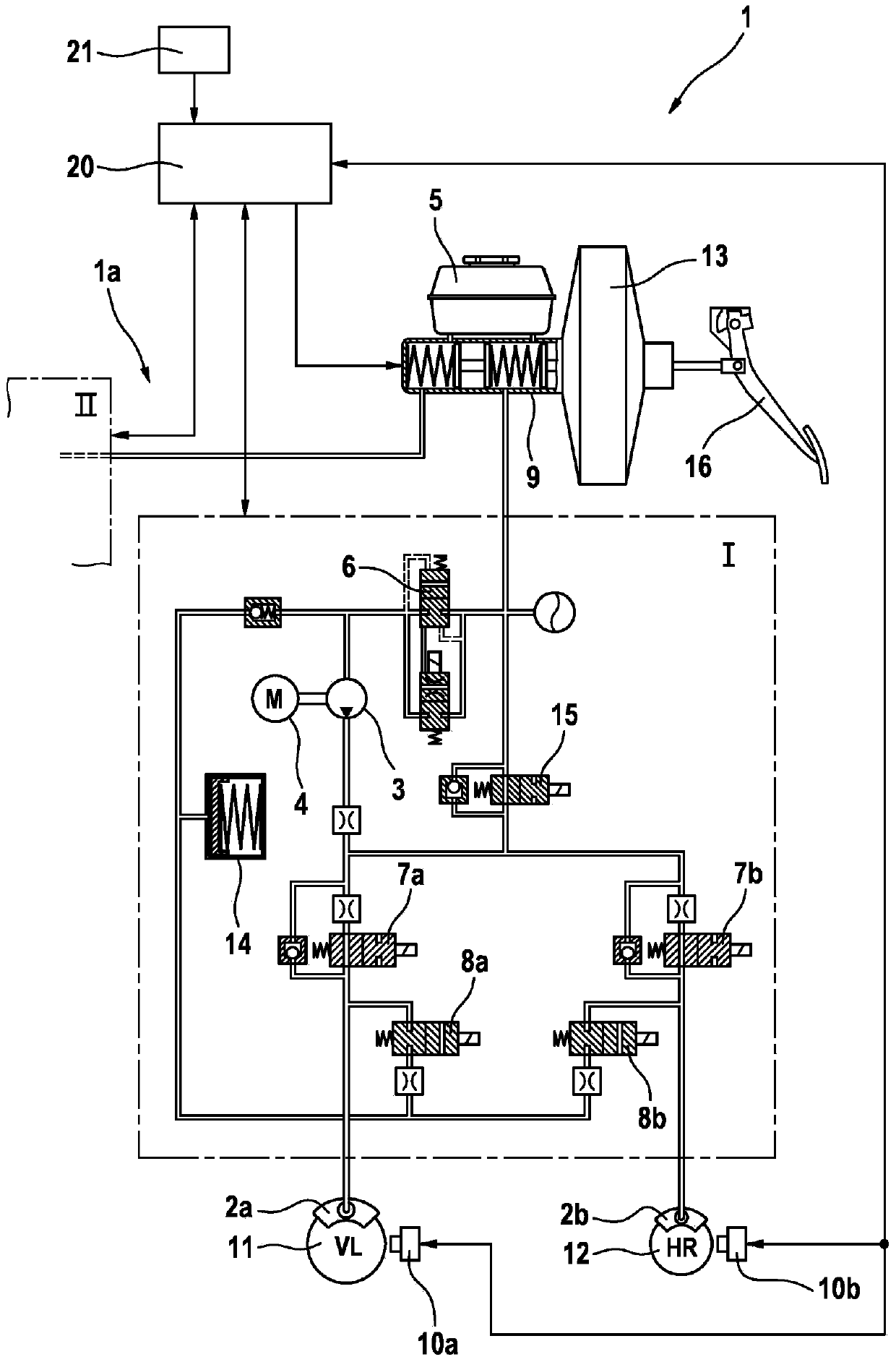
[0036] figure 1 An electronically regulated motor vehicle braking system 1 is shown, which has a brake system 1 a of the motor vehicle with a control device 20 of a driving dynamics control system (ESC system) , the sensor data of the ESC sensor 21 are fed to the control unit.

[0037] The control device 20 controls the braking system 1a, wherein figure 1 Only the brake circuit I connected to the brake cylinder (tandem master cylinder) 9 is shown for the left front wheel 11 and the right rear wheel 12; the second brake circuit II is correspondingly configured and also connected to the brake cylinder 9 and is only briefly shown. The wheel brakes 2a or 2b of the wheels 11 and 12 are respectively connected to the brake circuit I via hydraulic lines.

[0038] The brake system 1 has a brake booster 13 connected to the brake cylinder 9 and a storage tank 5 for brake fluid or hydraulic fluid. Brake cylinder 9 generates a brake pressure P as pilot pressure on the output side in re...


PUM


Abstract

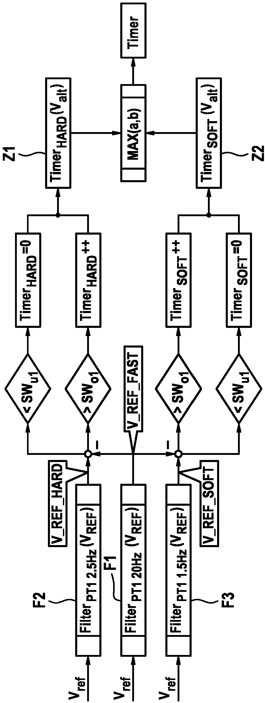
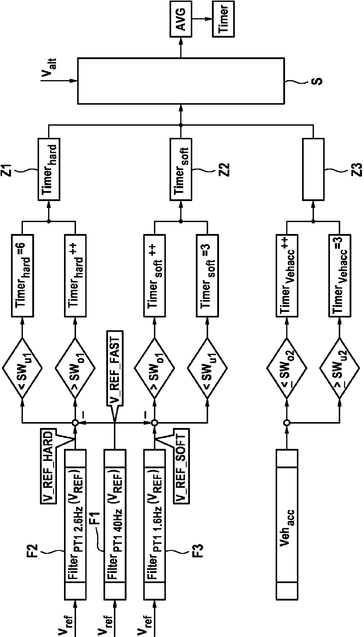
The invention relates to a method for determining a model upstream pressure (PTHZ-mod) by means of a mathematical model in an electronically regulated motor vehicle brake system (1), in which method a regulation of an electrically controllable hydraulic brake valve (7a, 7b) effecting a braking pressure buildup on at least one wheel brake (2a, 2b) is performed using the model upstream pressure (PTHZ-mod) as at least one parameter, and wheel sensors (10a, 10b) for determining a vehicle speed signal indicating the vehicle speed, and an operable brake pedal (16) are provided; according to the invention at least one first low-pass filtered speed signal (vref-fast, Vref-hard, Vref-soft) is generated from the vehicle speed signal (Vref) by means of a low-pass filter (F1, F2, F3) with a first limit frequency (fg1, fg2, fg3), from the temporal progression of which filtered signal the time (t1) of a significant decrease of speed is detected, which is used as a starting criterion to determine a period of time (timer) beginning with a vehicle deceleration initiated by a braking process and ending at the time (t2) when regulation of the braking process begins, and to classify the actuation speed of the brake pedal (16), the period of time (Timer) is compared to at least one first threshold value (SW1, SW2), and finally a model upstream pressure (PTHZ-mod) is determined by means of the mathematical model on the basis of the comparison result.

Description

technical field [0001] The invention relates to a method according to the preamble of claim 1 for determining a model pilot pressure in an electronically regulated motor vehicle brake system by means of a mathematical model. Background technique [0002] In addition to the basic function ABS, the electronic vehicle braking system usually includes other functions, such as driving slip regulation (ASR), driving stability regulation (ESP), distance regulation (ACC), etc., depending on the configuration plan. The function partly utilizes the sub-function of the ABS regulation system. [0003] There are various costly variants of the motor vehicle braking system on the market; here, in the sense of the present invention, there can be mentioned braking systems which can be implemented without pressure sensors brake regulation task. In fact, all internal calculation variables required for brake regulation are obtained on the basis of wheel speed sensors connected to the brake sys...

Claims


Application Information

Patent Timeline
Patent Type & Authority Applications(China)
IPC IPC(8): B60T8/172B60T8/1755
CPCB60T8/4872B60T2270/204B60T2270/14B60T2270/308B60T8/17551B60T8/172
Inventor M·施泰因J·齐默尔曼D·布克哈特J·博尔内斯
Owner CONTINENTAL TEVES AG & CO OHG
Learn More