Tubular flame burner
A flame burning, tubular technology, applied in the direction of burners, gas fuel burners, combustion chambers, etc., can solve problems such as flameout
- Summary
- Abstract
- Description
- Claims
- Application Information
AI Technical Summary
Problems solved by technology
Method used
Image

Examples
Embodiment approach 1
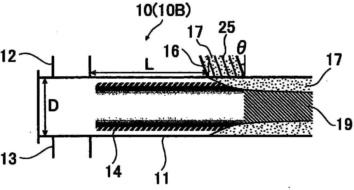
[0062] image 3 shows the tubular flame burner 10B according to Embodiment 1 of the present invention, Figure 4 It is a transverse cross-sectional view showing the installation state of the temperature adjustment gas injection nozzle 16 of the tubular flame burner 10B.
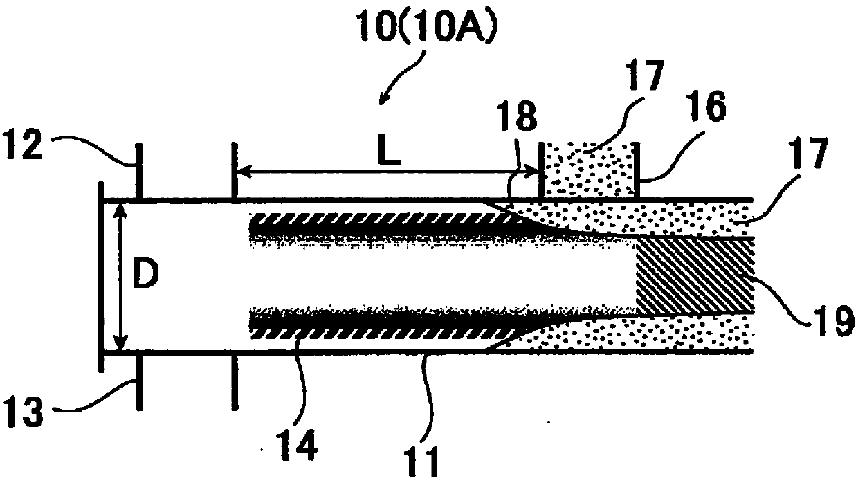
[0063] In the tubular flame burner 10B of this Embodiment 1, preventing such as figure 2 As shown, a part 18 of the temperature adjustment gas 17 flows back to the upstream side.
[0064] That is, if image 3 As shown, the temperature adjustment gas injection nozzle 16 is installed at an angle θ so that the temperature adjustment gas 17 is blown in a direction inclined at a predetermined angle θ toward the downstream side from a direction perpendicular to the tube axis of the tubular combustion chamber 11 . Specifically, the angle θ is set to 10° to 60° (10°≦θ≦60°). The angle θ is preferably 25° to 60°.
[0065] In addition, it was confirmed by numerical simulation that when the angle θ is 10° or more, ...
Embodiment approach 2
[0075] Figure 11 , Figure 12 , Figure 13 The tubular flame burners 10C, 10D, and 10E according to Embodiment 2 of the present invention are shown, respectively.
[0076] In the tubular flame burners 10C, 10D, and 10E of Embodiment 2, the position where the combustion of the tubular flame 14 is actively accelerated to complete the combustion is moved upstream from the position where the combustion is naturally completed, and is provided on the downstream side. Gas for temperature adjustment is blown into the nozzle 16 .
[0077] That is, a turbulent flow generating mechanism 20 is provided on the downstream side of the tubular flame 14 and upstream of the temperature-adjusting gas injection nozzle 16, so that the temperature of the tubular flame 14 will not decrease due to the backflow of the temperature-adjusting gas 17, and accelerate to a high temperature. The oxygen and fuel gas are mixed and burned, so that the combustion is forcibly completed.
[0078] Specifically...
Embodiment 1
[0092] As Example 1 of the present invention, using Figure 17 The shown combustion test apparatus 30 is for confirming the performance of the tubular flame burner 10B according to Embodiment 1 of the present invention described above.
[0093] At this time, as the fuel gas of the tubular flame burner 10 installed in the furnace body 31, dilute LPG (diluted propane gas, calorific value of 2400 kcal / Nm) obtained by diluting LPG (propane gas) to 10 times with nitrogen was used 3 ), air was used as the oxygen-containing gas. The sizes of the fuel gas injection nozzle 12 and the oxygen-containing gas injection nozzle 13 are respectively adjusted so that the velocity of the fuel gas injected toward the tangential direction of the inner wall surface of the combustion chamber 11 and the velocity of the air become within the combustion chamber 11. Approximately 9 times the gas velocity after mixing.
[0094] In addition, as the gas 17 for temperature adjustment, three kinds of dilut...
PUM
 Abstract
Description
Claims
Application Information
 - R&D
- Intellectual Property
- Life Sciences
- Materials
- Tech Scout
- Unparalleled Data Quality
- Higher Quality Content
- 60% Fewer Hallucinations
Browse by: Latest US Patents, China's latest patents, Technical Efficacy Thesaurus, Application Domain, Technology Topic, Popular Technical Reports.
© 2025 PatSnap. All rights reserved.Legal|Privacy policy|Modern Slavery Act Transparency Statement|Sitemap|About US| Contact US: help@patsnap.com