A riveting head structure for plunger steel ball riveting

A technology of riveting head and steel ball, which is applied in metal processing, metal processing equipment, manufacturing tools, etc., can solve the problems of damaged steel ball riveting, indenter cannot change the structure, and is not firm, so as to avoid damage, simple structure, The effect of improving riveting efficiency

Active Publication Date: 2016-04-20
无锡创捷汽车部件有限公司
View PDF5 Cites 0 Cited by
  • Summary
  • Abstract
  • Description
  • Claims
  • Application Information

AI Technical Summary

Problems solved by technology

At present, in order to meet the needs of customers, the steel balls installed in the plunger need to be riveted to achieve the purpose of tight fit between the two. However, the existing riveting presses are prone to steel balls after riveting because the pressure head cannot change the structure. Damaged or weak riveting occurs, so it is urgent to design a riveting head structure for plunger steel ball riveting

Method used


Image

  • A riveting head structure for plunger steel ball riveting
  • A riveting head structure for plunger steel ball riveting
  • A riveting head structure for plunger steel ball riveting

Examples


Embodiment Construction

[0017] The specific implementation manner of the present invention will be described below in conjunction with the accompanying drawings.

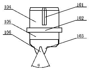
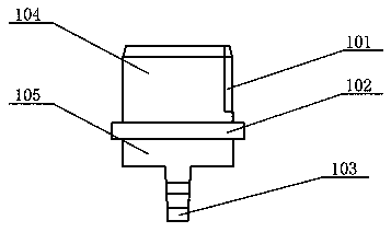
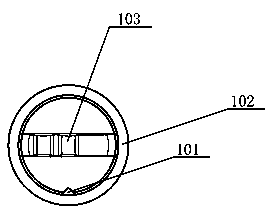
[0018] Such as figure 1 , figure 2 As shown, a riveting head structure for plunger steel ball riveting, which is formed by connecting an upper pressing body 104 and a lower pressing body 105, and is located at the joint of the upper pressing body 104 and the lower pressing body 105 outward along the circumferential direction The flange 102 is extended to form an opening 101 on the upper pressing body 104 , and the opening 101 is vertically arranged on the upper pressing body 104 . A plurality of bosses 103 arranged at intervals are formed on the lower pressing body 105 . The flange 102 , the upper pressing body 104 and the lower pressing body 105 are all circular. The longitudinal section of the bosses 103 is conical, and the slopes of the bosses 103 form a positioning angle α for abutting against the surface of the plunger steel ball....


PUM


Abstract

The invention relates to a riveting head structure for riveting of a plunger steel ball. The riveting head structure is formed in the mode that an upper pressing body and a lower pressing body are connected into a whole. A flange is formed at the joint of the upper pressing body and the lower pressing body in an outwards extending mode in the circumferential direction. The upper pressing body is provided with an opening. The lower pressing body is provided with multiple bosses which are arranged at intervals. The riveting head structure is simple and convenient to install; since the upper pressing body is provided with the opening, a fastener can be in contact with the opening, and firmness and reliability of connection between the riveting head structure and a riveting machine are guaranteed; meanwhile, accurate locating between the riveting head structure and a pressing rod of the riveting machine can be realized through the flange; due to the arrangement of the bosses, the contact area between the riveting head structure and the steel ball can be maximized through a locating angle, damage to the surface of the steel ball is avoided, and riveting efficiency is also improved.

Description

technical field [0001] The invention relates to riveting equipment, in particular to a riveting head structure for plunger steel ball riveting. Background technique [0002] The riveting press uses the stamping machine equipment and the special connecting die to go through an instantaneous high-pressure processing process, and according to the cold extrusion deformation of the plate itself, a stress-free internal mosaic dot with a certain tensile and shear strength is formed. Two or more layers of boards of different materials and different thicknesses can be connected. At present, in order to meet the needs of customers, the steel balls installed in the plunger need to be riveted to achieve the purpose of tight fit between the two. However, the existing riveting presses are prone to steel balls after riveting because the pressure head cannot change the structure. Damaged or weak riveting occurs, so it is urgent to design a riveting head structure for plunger steel ball riv...

Claims


Application Information

Patent Timeline
Patent Type & Authority Patents(China)
IPC IPC(8): B23P19/02
CPCB23P19/02
Inventor 周一峰陈兵兵
Owner 无锡创捷汽车部件有限公司
Why Eureka
Try Eureka