Locating device for line pipe groove machining

A groove processing and positioning device technology, applied in positioning devices, clamping devices, metal processing equipment and other directions, can solve the problems of loose clamping of pipe fittings, falling of pipe fittings, large interaction force, etc., to improve the clamping force, Guaranteed efficiency

Active Publication Date: 2014-06-18
李勤余
View PDF6 Cites 7 Cited by
  • Summary
  • Abstract
  • Description
  • Claims
  • Application Information

AI Technical Summary

Problems solved by technology

[0003] However, in the actual beveling process, in order to improve the processing efficiency, the method of clamping and rotating cutting is usually used for tubular workpieces. However, when the cutting tool contacts the edge of the pipe during cutting, a large interaction force will be generated, making the pipe The clamping is prone to loosening, which will cause the pipe fittings to fall in severe cases, which will cause certain damage to the beveling machine or the edge of the pipe fittings

Method used


Image

  • Locating device for line pipe groove machining

Examples


Embodiment 1

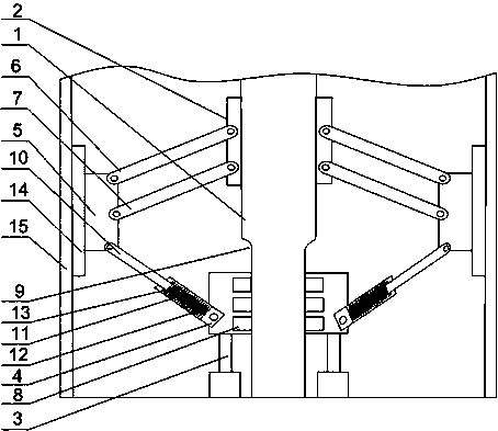
[0020] Such as figure 1 As shown, the wire pipe bevel processing and positioning device of the present invention includes a central shaft 1, which is fixed on a lathe, and a fixed cylinder 2 is installed on the central shaft 1, and also includes a cylinder 3. The output of the cylinder 3 The end is connected with the central shaft 1 through the sliding tube, the sliding tube is arranged on the central shaft 1, the two ends of the sliding tube are hinged with the lower rod, the end of the lower rod is hinged with the swing arm 5, and the swing arm 5 passes through the upper swing rod 6 And the lower swing rod 7 is hinged with the fixed cylinder 2, the two ends of the central shaft 1 have grooves 9, and a plurality of rollers 8 are installed in the sliding cylinder 4, and the rollers 8 are slidably arranged in the grooves 9. When the present invention is used, the pipe fitting 15 is first set outside the central shaft 1, the cylinder 3 is adjusted so that its output end moves up...

Embodiment 2

[0022] Such as figure 1 As shown, on the basis of Embodiment 1, the present embodiment includes a support rod 10 and a sleeve 11, the sleeve 11 is installed on the slider 4, the support rod 10 is sleeved in the sleeve 11, and the support rod 10 A limit ring 13 is arranged on it, and the limit ring 13 is connected with the sliding cylinder 4 through a spring 12 . When the cutting tool rotates the edge of the pipe fitting 15, the pipe fitting 15 body will vibrate to a certain extent, which will cause a certain impact on the swing arm 5 and the upper and lower swing rods 7, and may cause the upper swing rod 6 and the lower swing rod 7 in serious cases break; when the support rod 10 is stressed, the support rod 10 moves downward in the casing 11, and the spring 12 is compressed to generate an elastic force opposite to the direction of the force, so that the support rod 10 is balanced in force, and the limit ring 13 can Prevent the support rod 10 from being pulled excessively when...

Embodiment 3

[0024] Such as figure 1 As shown, in this embodiment, on the basis of Embodiment 1, the end surface of the swing arm 5 away from the central axis 1 is an arc surface; the arc surface is provided with a backing plate 14, and the arc of the backing plate 14 The surface area is greater than that of the arc surface of the swing arm 5; the roller 8 is a rubber wheel. When clamping the inner wall of the pipe fitting 15, the swing arm 5 is in contact with the inner wall of the pipe fitting 15, and the swing arm 5 on the arc surface can be completely attached to the inner wall of the pipe fitting 15, thereby improving the clamping force of the swing arm 5 on the pipe fitting 15; The backing plate 14 provided on the top can further increase the contact area with the inner wall of the pipe fitting 15 to ensure the stability of clamping.

[0025] Preferably, the rubber wheel can be deformed to a certain extent after the sliding cylinder 4 is subjected to stress, and the reaction force g...


PUM


Abstract

The invention discloses a locating device for line pipe groove machining. The locating device for the line pipe groove machining comprises a central shaft, the central shaft is fixed on a turning lathe, and a fixed barrel is mounted on the central shaft. The locating device for the line pipe groove machining further comprises an air cylinder, the output end of the air cylinder is connected with the central shaft through a sliding barrel, a sliding barrel is arranged on the central shaft, lower links are connected to the two ends of the sliding barrel through hinges, swinging arms are connected to the ends of the lower links through hinges, the swinging arms are hinged to the fixed barrel through an upper oscillating bar and a lower oscillating bar, grooves are formed in the two ends of the central shaft, multiple rolling wheels are mounted in the sliding barrel, and the rolling wheels are arranged in the grooves in a sliding mode, and the upper oscillating bar, the lower oscillating bar, the lower links and the central shaft form a triangular frame. According to the principle that a triangle is highest in stability, the swinging arms can provide stable clamping force for the inner wall of the pipe fittings, and the efficiency for processing grooves of pipe fittings is guaranteed.

Description

technical field [0001] The invention relates to a profile cutting machine, in particular to a line pipe bevel processing and positioning device. Background technique [0002] The steel plate groove machine is used for deburring and groove processing of metal plates before welding. This machine mainly uses the principle of rolling washing to wash and cut the edge of the steel plate according to the required angle to obtain the groove required for welding. It is suitable for steel , cast iron, hard plastics, non-ferrous metals and other materials. The beveling machine is a special tool for chamfering and beveling pipes or flat plates on the front end of welding. Simple, standard angle, smooth surface and so on. The beveling machine has a variety of specifications, and it is an advanced tool provided for professional installation, maintenance and other work in industries such as electric power, petroleum, chemical industry, shipbuilding, and steel structure. This tool can gre...

Claims


Application Information

Patent Timeline
Patent Type & Authority Applications(China)
IPC IPC(8): B23Q3/00
CPCB23Q3/00B23Q2703/10
Inventor 陈怀之王刚聂海涛张仁友胡国波
Owner 李勤余
Why Eureka
Try Eureka