Wind turbine blade mold with double vacuum systems and method for making wind turbine blade by wind turbine blade mold

A wind rotor blade and double vacuum technology, applied in the field of machining molds, can solve the problems of inability to guarantee, difficult to improve production efficiency, poor process controllability, etc., and achieve the effects of improving product quality, saving labor costs, and saving process costs.

Inactive Publication Date: 2014-06-18
AVIC HUITENG WINDPOWER EQUIP
View PDF9 Cites 8 Cited by
  • Summary
  • Abstract
  • Description
  • Claims
  • Application Information

AI Technical Summary

Problems solved by technology

Therefore, in the process of making a wind turbine blade every time, it is difficult to ensure the airtightness of the sealed environment formed between the glue storage tank 7, the glue injection pipe 8, the mold 1, the vacuum pipe 9, the vacuum pump 10, and the resin collector. meet certain requirements
[0006] In this method of the prior art, an external vacuum system is temporarily composed of a rubber storage tank, a resin collector and a vacuum suction pipe every time, and then connected to the mould, so the external vacuum system itself and the external vacuum system cannot be guaranteed each time. The connection between the system and the mold has sufficient airtightness, and it is necessary to do a pressure-holding test before each blade is made. This method is more cumbersome, and it increases the difficulty of operation for workers, and it is difficult to improve production efficiency.
And part of the air extraction system cannot be reused, which virtually increases the manufacturing cost of the wind rotor blades
[0007] In addition, the resin collector used in the external vacuum system in the prior art is made of metal, and it is impossible to see whether the glue in the resin collector is almost full, and it is easy to cause the product to be scrapped due to the overflow of glue in the collector.
In addition, in the prior art, because the number of resin collectors used in the entire vacuum system is small, and it is impossible to judge whether the amount of glue injected at each glue injection point is appropriate during the production process, it is impossible to effectively and timely control the glue injection speed , making the process less controllable

Method used


Image

  • Wind turbine blade mold with double vacuum systems and method for making wind turbine blade by wind turbine blade mold
  • Wind turbine blade mold with double vacuum systems and method for making wind turbine blade by wind turbine blade mold
  • Wind turbine blade mold with double vacuum systems and method for making wind turbine blade by wind turbine blade mold

Examples


Embodiment Construction

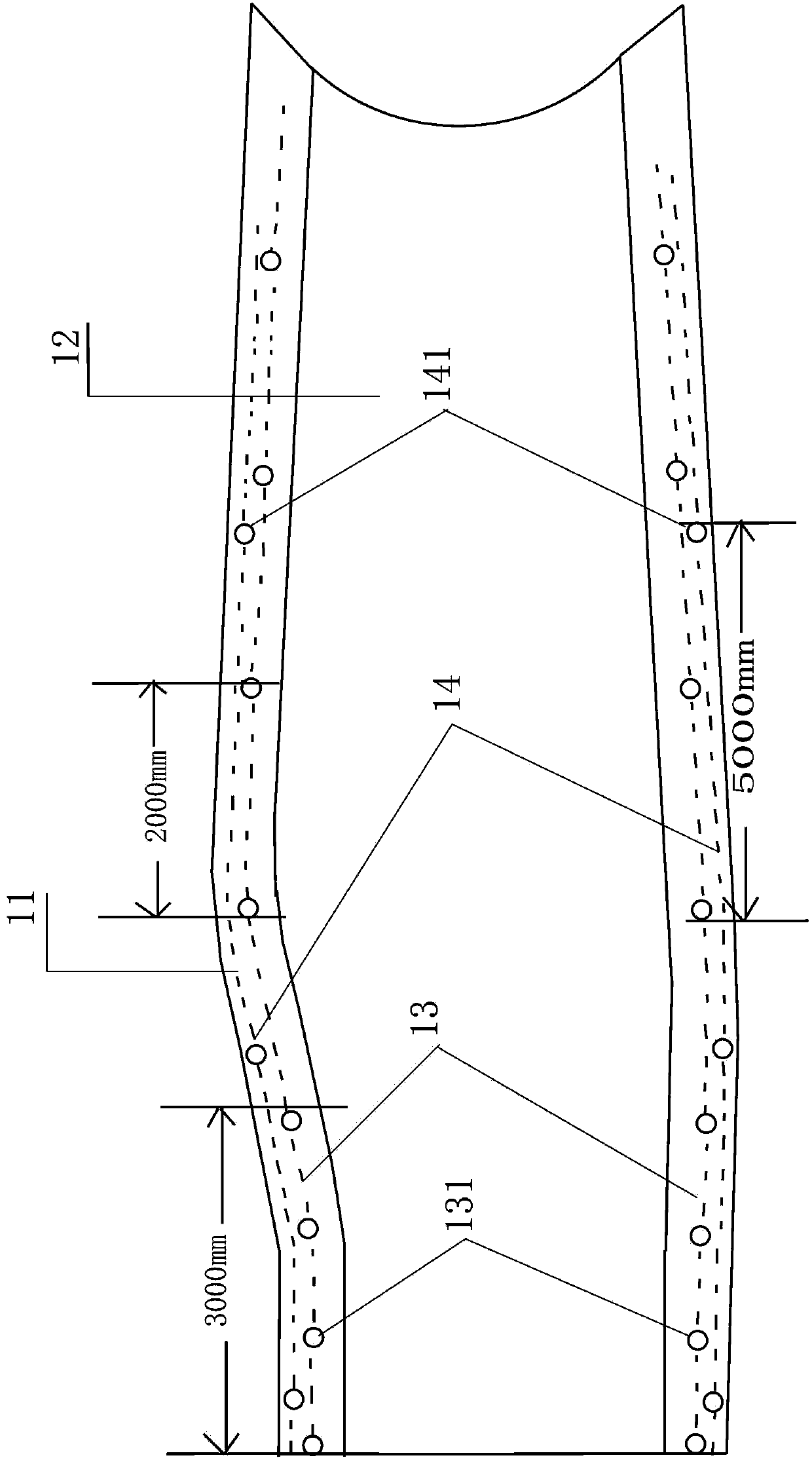
[0036] Such as figure 2 As shown, it is a schematic diagram of double vacuum air passages on the parting surface of the wind turbine blade mold of the present invention.

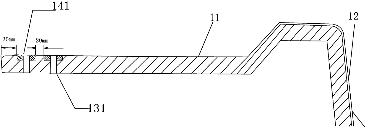
[0037] in figure 2 Shown in is a top view of the wind turbine blade mold, including a parting surface 11 in the mold 1, which is a surface where the upper mold and the lower mold are matched and joined with each other, and the inner side of the parting surface 11 is a mold cavity 12. A first vacuum air passage 13 and a second vacuum air passage 14 are formed on the parting surface 11 . Wherein the first vacuum air channel 13 is relatively located inside the parting surface 11, and the second vacuum air channel 14 is relatively located outside the parting surface 11, and the first vacuum air channel 13 and the second vacuum air channel 14 respectively include several intervals. The air extraction points 131 and 141 of each air extraction point 131 and 141 are perforations penetrating the parting surface. ...


PUM


Abstract

The invention provides a wind turbine blade mold with double vacuum systems and a method for making a wind turbine blade by the wind turbine blade mold. A first vacuum gas passage is connected to a resin collector by a pipe. A second vacuum gas passage is connected to vacuum extraction equipment by a pipe. The first vacuum gas passage and the second vacuum gas passage are connected respectively to the fixed vacuum pipes and vacuum extraction equipment. Before manufacture of the wind turbine blade mold, a pressure maintaining test is carried out. Compared with the prior art needing temporary establishment of an external vacuum system, the method provided by the invention saves a labor cost and improves product quality. The resin collector is made of a transparent material and the vacuum pipes are provided with multiple air exhaust points and are distributed at different positions of the wind turbine blade mold so that through observation of an increasing rate of a resin amount of the resin collector, it is easily determined if injecting rates at all injecting points are too fast, product process controllability is improved, collected overflowing resin can be directly recovered and recycled and a wind turbine blade manufacture cost is saved.

Description

technical field [0001] The invention relates to a mold for mechanical processing, in particular to a mold for making wind rotor blades and a method for producing wind rotor blades using the mold. Background technique [0002] Under the circumstance that traditional petrochemical energy is increasingly scarce, environmentally friendly, green and reusable energy has become the main energy situation advocated at present. Therefore, many windy areas in my country have gradually added wind power generation devices. For wind turbines, the wind rotor blades are an important part of the wind turbine. For the production of wind blades, the traditional hand lay-up process has the disadvantages of low efficiency, unstable quality of finished products, and inaccurate production. At the same time, it is highly dependent on the proficiency of personnel and environmental conditions. Therefore, manufacturers of wind rotor blades at home and abroad generally use a vacuum injection process...

Claims


Application Information

Patent Timeline
IPC IPC(8): B29C33/10B29C70/36B29L31/08
CPCB29L2031/085Y02P70/50
Inventor 张旭李小波丁晓春张立新杨鹏飞赵亚微陈志强刘智远张俊婷
Owner AVIC HUITENG WINDPOWER EQUIP
Why Eureka
Try Eureka