
Axle counter installation test detector

A detection device, axle counting equipment technology, applied in the direction of measuring devices, optical devices, vehicle route interaction equipment, etc., can solve the problem of affecting the entire process and working time of equipment detection and debugging, installation and test inspection can not be carried out at the same time, installation Inaccurate standards and other issues, to achieve the effect of small error, simple structure, and labor saving

Active Publication Date: 2014-06-18
ELECTRICAL ENG CO LTD OF CTCE GRP
View PDF4 Cites 4 Cited by
  • Summary
  • Abstract
  • Description
  • Claims
  • Application Information

AI Technical Summary

Problems solved by technology

Using specially measured simulated train wheels to simulate driving has many human factors. It may be due to manual errors that the driving wheels are not simulated well, which may cause interference to the magnetic head and high error rate. It is necessary to recount the axle and reset the magnetic head to restart the debugging work, which affects the debugging. efficiency
During the installation inspection process, the installation standards are often inaccurate due to manual errors
In addition, the previous detection and acceptance devices cannot be installed and tested at the same time. The success rate of the test is low and the work efficiency is low. Once a mistake is made, it is likely to cause a new test.
There are many personnel for indoor and outdoor testing and communication transmission, because outdoor simulation and testing devices affect the entire process and working hours of equipment testing and debugging

Method used


Image

  • Axle counter installation test detector
  • Axle counter installation test detector
  • Axle counter installation test detector

Examples


Embodiment Construction

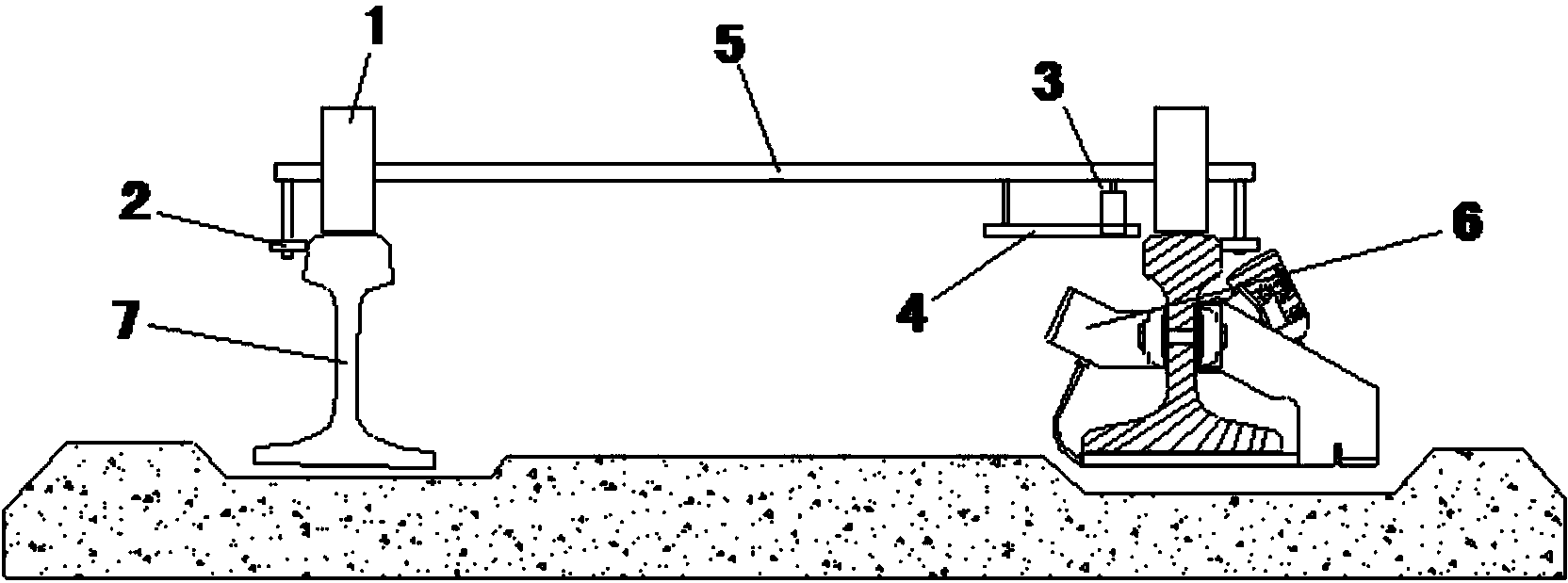
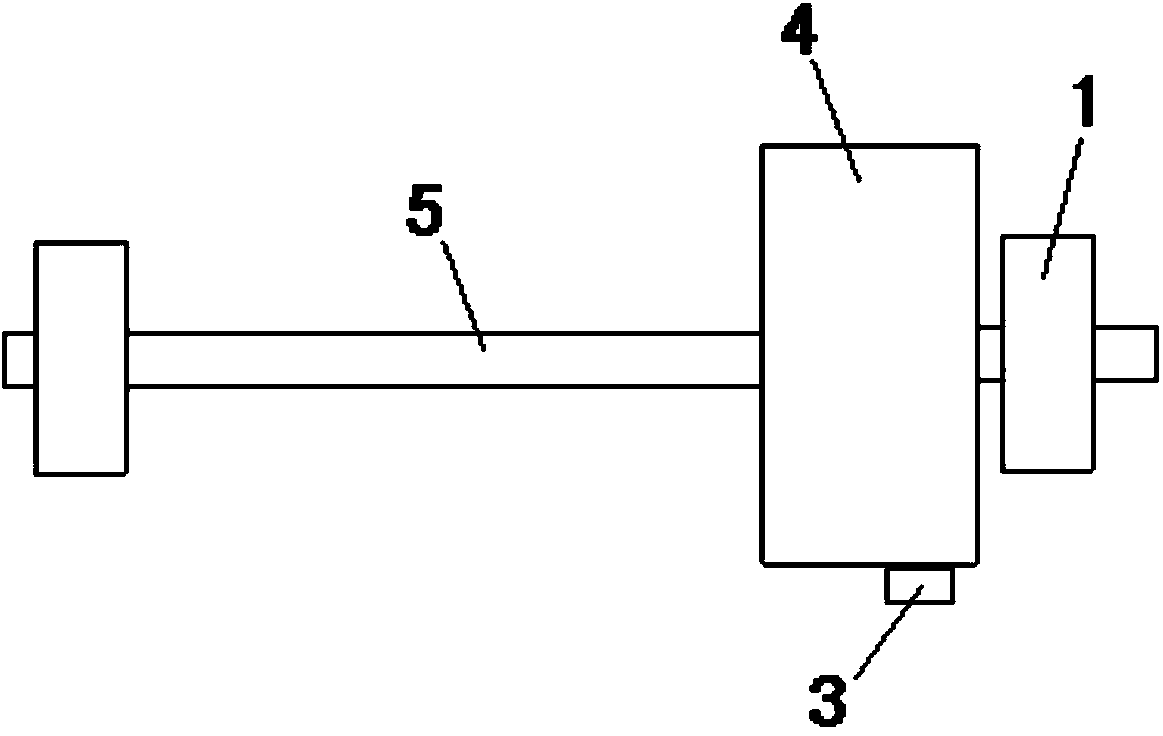
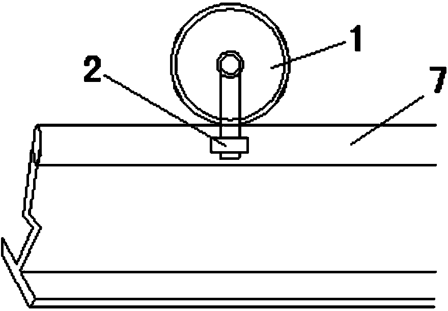
[0018] like Figure 1-Figure 4 shown. Axle counting equipment installation test detection device, including a running wheel smooth connection shaft 5 horizontally placed above a pair of rails 7 to be tested, a pair of running wheels 1 are installed on the running wheel stable connection shaft 5, and the two running wheels 1 are respectively placed to be tested On the top surface of the rail 7, the two ends of the running wheel stable connection shaft 5 are respectively vertically downwardly connected with a positioning shaft. Attached to the side surface of the rail 7 to be tested, the bottom of the running wheel stable connection shaft 5 is connected to a simulated wheel pair test board 4, and the front end of the simulated wheel pair test board 4 is equipped with an infrared height measuring device that cooperates with the axle counting magnetic head sensor 6 on the rail 7 to be tested Instrument 3.

[0019] The lower surface of the simulated wheel pair test board 4 is at ...


PUM


Abstract

The invention discloses an axle counter installation test detector, which comprises a steady traveling wheel connecting axle, two traveling wheels are rotatably mounted on the steady traveling wheel connecting axle and respectively arranged on the top surfaces of rails to be detected, small traveling direction positioning wheels are respectively rotatably mounted on both ends of the steady traveling wheel connecting axle, moreover, the rims of the two small traveling direction positioning wheels respectively cling to the side surfaces of the rails to be detected, a simulated wheel pair test board is connected with the bottom of the steady traveling wheel connecting axle, and an infrared height measuring instrument is mounted on the front end of the simulated wheel pair test board. The axle counter installation test detector can detect whether the installation height of an axle counter magnetic head sensor comes up to a standard and an acceptance specification, can simulate the running direction and wheel pair of a train and has the advantages of more accurate detection and minor error.

Description

technical field [0001] The invention relates to the field of railway rail detection devices, in particular to an axle counting equipment installation test detection device for railway signal control vehicles. Background technique [0002] At present, there is no fixed molded product for the installation test and detection of outdoor axle counting equipment for railway signals in China, and there are three methods for outdoor axle counting detection. Use a scale to measure the height of the magnetic head sensor from the rail surface with the naked eye, use specially measured simulated train wheels to simulate driving, and use a trolley with a metal wheel set for test detection. [0003] Using a scale to directly measure and observe the height of the shaft magnetic head sensor from the rail surface, there are many human factors, and the error is large by naked eye observation. Using specially measured simulated train wheels to simulate driving has many human factors. It may b...

Claims


Application Information

Patent Timeline
IPC IPC(8): B61L1/16G01B11/02
Inventor 陈先伟赵向沈振程家毛王宇
Owner ELECTRICAL ENG CO LTD OF CTCE GRP
Learn More