Supercharge Your Innovation With Domain-Expert AI Agents!

Driving plate for driving steel wire rope pulley to rotate

A wheel-driven and wire-rope technology, applied in the field of wire-rope-driven rotary dials, can solve problems such as lack of a good solution, and achieve the effects of improving loading and unloading efficiency, reducing work intensity, and preventing rotation

Inactive Publication Date: 2014-06-18
UNIV OF JINAN
View PDF6 Cites 0 Cited by
  • Summary
  • Abstract
  • Description
  • Claims
  • Application Information

AI Technical Summary

Problems solved by technology

[0003] Currently, there is no good solution

Method used


Image

  • Driving plate for driving steel wire rope pulley to rotate
  • Driving plate for driving steel wire rope pulley to rotate
  • Driving plate for driving steel wire rope pulley to rotate

Examples


Embodiment Construction

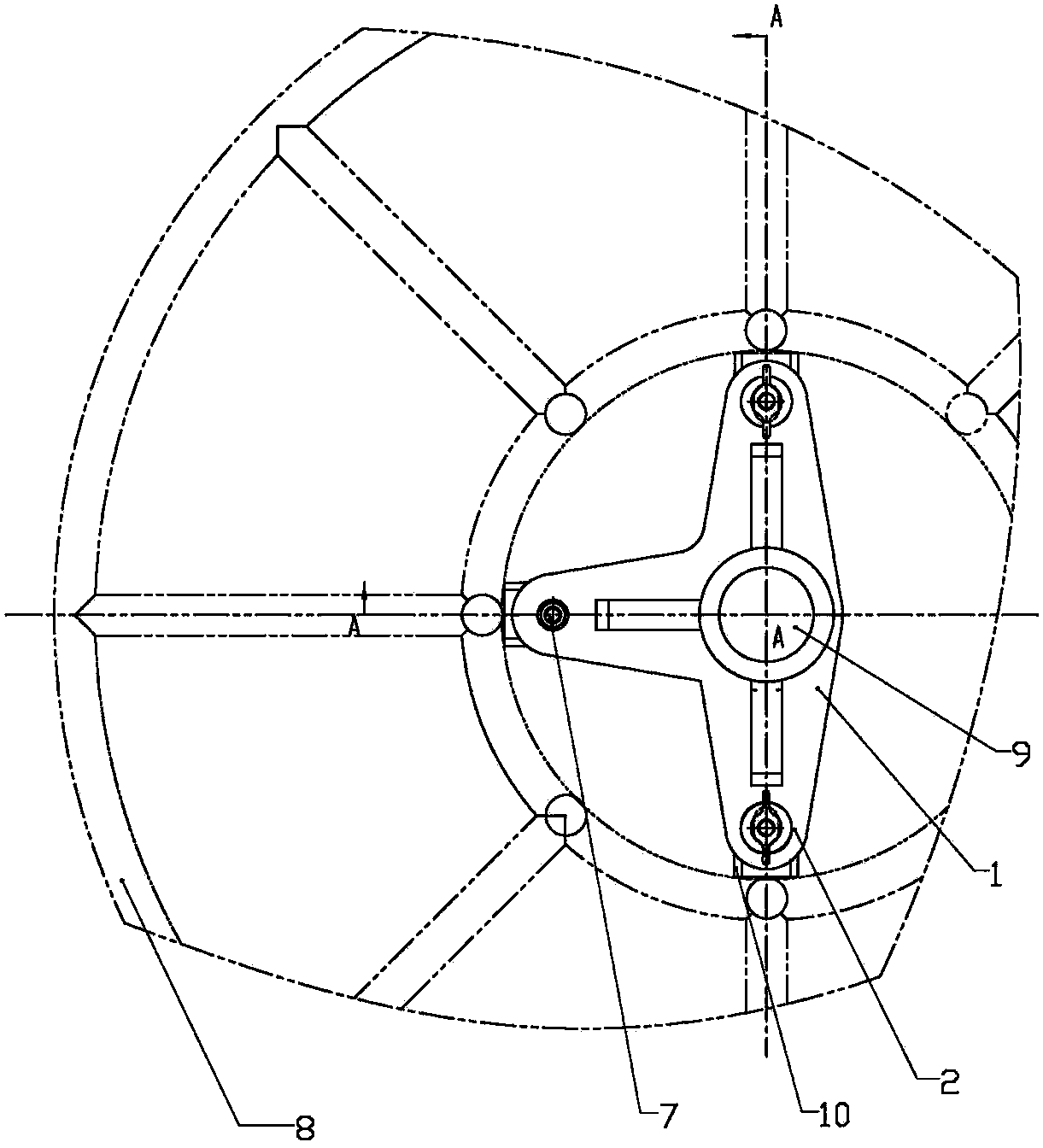
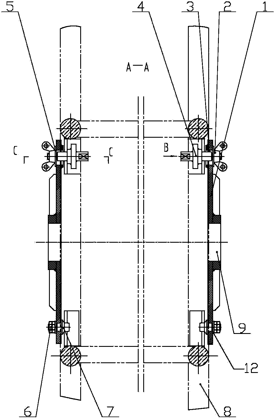
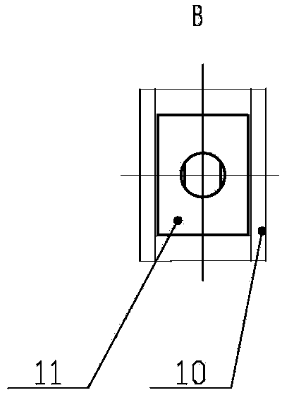
[0015] Refer to the attached figure 1 to attach Figure 4 The rotary dial driven by a wire sheave of the present invention will be described in detail below.

[0016] A wire sheave-driven rotary dial of the present invention, its structure includes a pair of "T" shaped dials 1, each of the dials 1 is fixedly connected to the sheave 8 through a channel steel 10, each of the The dial 1 is respectively provided with a circular positioning hole 12 and two oblong grooves 3, the two oblong grooves 3 are respectively located at the ends of the two arms of the dial 1 at 180 degrees, and the positioning hole 12 is located at the same The end of the support arm with a long circular groove of 90°, the channel steel 10 is arranged in the inner circular hole of the sheave 8 and is fixed with the sheave 8, and the channel steel 10 and the dial 1 pass through respectively The fixed bayonet 7 is connected with the movable bayonet 4, and one end of the fixed bayonet 7 is fastened on the dial...


PUM


Abstract

The invention discloses a driving plate for driving a steel wire rope wheel to rotate, and belongs to installation tools. The driving plate structurally comprises a pair of T-shaped driving plate bodies, each driving plate body is fixedly connected with a corresponding rope wheel through a steel channel, a round positioning hole and two oblong grooves are formed in each driving plate body, the steel channels are connected with the driving plate bodies through fixed clamping pins and movable clamping pins respectively, one end of each fixed clamping pin is fastened onto the corresponding driving plate body through a locking nut, the other ends of the fixed clamping pins are inserted into steel channel holes of the rope wheels, movable clamping pins penetrate through the steel channels and the oblong grooves in the driving plate bodies respectively, the movable clamping pins and the driving plate bodies are fixed through butterfly nuts, clamping holes are formed in the middles of the driving plate bodies, and the clamping holes are connected with pay-off and take-up equipment clamping devices. The driving plate has the advantages of achieving fastening of rope wheels of the same size, particularly deformed rope wheels of the same type and the T-shaped driving plate bodies, meanwhile achieving single-person rapid operation by matching the ends, of a rectangular structure, of the movable clamping pins with the steel channels welded onto the rope wheels, and completing assembly and disassembly of the installation tool of the driving plate.

Description

technical field [0001] The invention relates to a harness, in particular to a rotary dial driven by a wire rope pulley. Background technique [0002] Traction wire rope is widely used in power grid construction as a necessary tool for cable tension erection. However, due to the relatively harsh working environment of traction wire rope, it is easy to stick to dirt such as mud and sand, and it is prone to wear, fatigue, rust and broken wires during the working process. Defects seriously affect the safety of construction and shorten the life of the wire rope. Therefore, China's electric power industry standard "Anti-twist Wire Rope for Tension Stringing of Transmission Lines" (DL / T1079-2007) stipulates that the anti-twist wire rope for traction must be inspected and maintained every year. For inspection and maintenance, the steel wire rope on the sheave must be fully laid out, and the wire rope must be taken up after a series of cleaning, inspection and maintenance. The unwi...

Claims


Application Information

Patent Timeline
IPC IPC(8): B65H75/30
Inventor 蒋佳音唐陆
Owner UNIV OF JINAN
Features
  • R&D
  • Intellectual Property
  • Life Sciences
  • Materials
  • Tech Scout
  • Unparalleled Data Quality
  • Higher Quality Content
  • 60% Fewer Hallucinations
Learn More