
Mechanical expansion tool

A mechanical and tool technology, used in wellbore/well components, earth-moving drilling, etc., can solve problems such as pipe wear, and achieve the effects of easy operation, high strength and strong wear resistance

Active Publication Date: 2014-06-18
CHINA PETROLEUM & CHEM CORP +1
View PDF6 Cites 0 Cited by
  • Summary
  • Abstract
  • Description
  • Claims
  • Application Information

AI Technical Summary

Problems solved by technology

Although the tool has the function of grinding and milling, it will cause greater wear to the tube body of the expansion tube during mechanical expansion

Method used


Image

  • Mechanical expansion tool
  • Mechanical expansion tool

Examples


Embodiment Construction

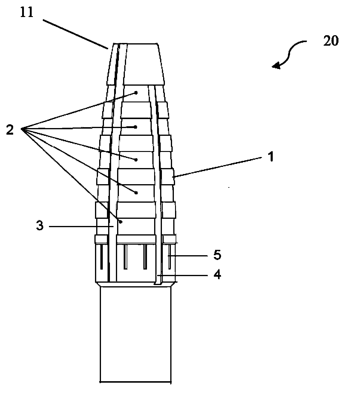
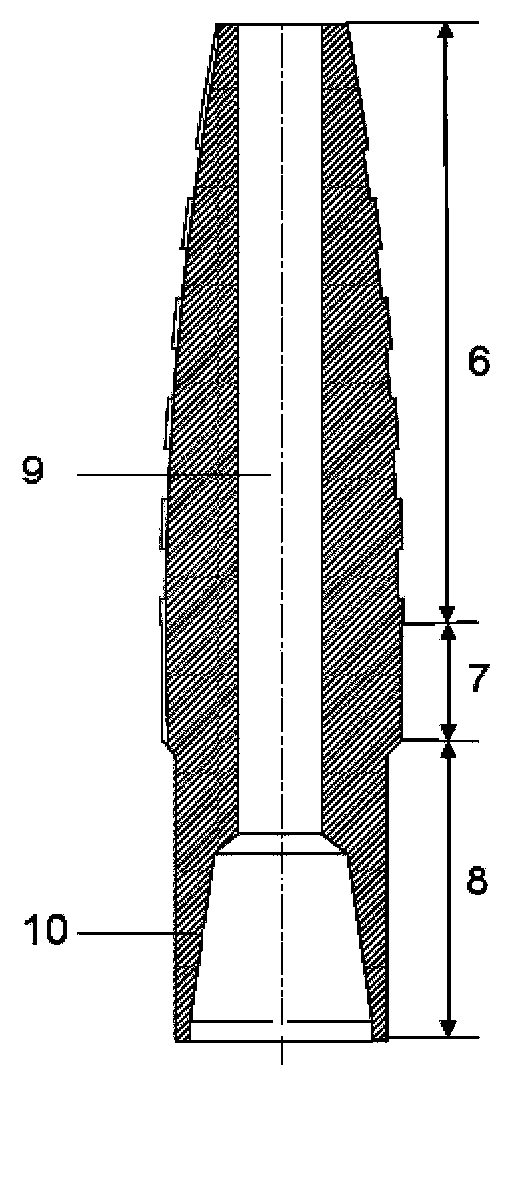
[0017] figure 1 with 2 A mechanical expansion tool 20 according to the invention is shown comprising a body 1 and an internal fluid channel 9 running through the body 1 . The body 1 can be made, for example, of drill pipe material. In some embodiments, the body can be made of E75, X95, G105 steel.

[0018] Such as figure 2 As shown, the body 1 includes three parts, namely the functional section 6 , the gage section 7 with a constant diameter and the connection section 8 . The connection section 8 can, for example, have an internal thread for connection to a drilling tool (not shown). However, it is easy to understand that the connection section 8 can also be connected with the drilling tool in other conventional ways.

[0019] The functional segment 6 of the body 1 is also referred to as an arc segment, which is a substantially arc-shaped component with a gradually decreasing diameter along the direction towards the free end 11 of the body 1 . Such as figure 1 As shown...


PUM


Abstract

The invention provides a mechanical expansion tool which comprises a body and an axial flow passage formed in the body. The body comprises a roughly arc functional section, a constant-diameter gauge protection section and a connecting section for being connected with a drilling tool, wherein the functional section comprises a plurality of angular slots formed in the outer surface; and ring parts are respectively arranged in all the angular slots.

Description

technical field [0001] The invention belongs to the field of petroleum drilling, and in particular relates to a mechanical expansion tool used in the technology of expansion bellows. Background technique [0002] Expansion bellows technology is a new technology used in drilling, completion or workover construction. In this technology, the bellows pipe string is lowered into the well, and the pipe string is permanently deformed into a round pipe by means of hydraulic and mechanical force, so as to realize the isolation of complex formations and the repair of damaged casings. The original borehole size is still maintained. Among them, after the expansion bellows is hydraulically expanded, a mechanical expander needs to be lowered to mechanically expand and repair the bellows. [0003] However, when complex situations are encountered, the expansion bellows may not be able to reach the expected size during the hydraulic expansion process. At this time, it is necessary to use ...

Claims


Application Information

Patent Timeline
Patent Type & Authority Applications(China)
IPC IPC(8): E21B29/10
Inventor 陶兴华陈天成曾义金刘鹏胡彦峰涂玉林白彬珍黄河淳李光泉王甲昌张海平詹美玲刘晓丹张仁龙
Owner CHINA PETROLEUM & CHEM CORP
Learn More