
A magnetorheological fluid self-generating transmission device driven by shape memory alloy

A technology of memory alloy and magnetorheological fluid, which is applied in the direction of clutches, fluid clutches, mechanical equipment, etc., can solve the problem of less research on the joint application of shape memory alloy and magnetorheological fluid in the adaptive adjustment of magnetorheological fluid transmission devices , to achieve the effect of self-adaptive adjustment, compact structure and reliable transmission performance

Inactive Publication Date: 2016-05-25
CHONGQING UNIV OF TECH
View PDF6 Cites 0 Cited by
  • Summary
  • Abstract
  • Description
  • Claims
  • Application Information

AI Technical Summary

Problems solved by technology

[0004] In summary, although researchers have done a lot of research on the individual applications of magnetorheological fluids and shape memory alloys in the field of transmission engineering, the research on the combined application of shape memory alloys and magnetorheological fluids in transmissions and the magnetic flow There is still little research on the self-adaptive regulation of variable fluid transmission

Method used


Image

  • A magnetorheological fluid self-generating transmission device driven by shape memory alloy

Examples


Embodiment 1

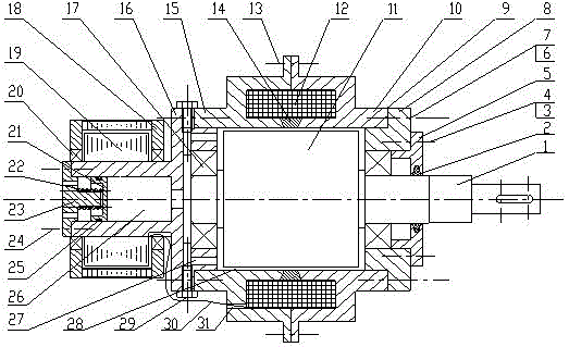
[0021] see figure 1 , a magneto-rheological fluid self-generating transmission device driven by a shape memory alloy, including a driving part, a driven part, an excitation coil 12 and a DC generator, wherein the driving part includes a driving shaft 1 and a driving inner cylinder 11, and the driving The shaft 1 is connected with the power device, and the driving shaft 1 can rotate under the drive of the power device. In this embodiment, the right end of the driving shaft 1 has a keyway, and the driving shaft 1 and the power device are connected by a key; the driving inner cylinder 11 is sleeved on the drive shaft 1 and can rotate synchronously with the drive shaft 1. Of course, the active inner cylinder 11 and the drive shaft 1 can also be integrally structured.

[0022]The driven part includes a driven shell, a left end cover 16 and a right end cover 8, the driven shell is sleeved outside the active inner cylinder 11, the left end cover 16 and the right end cover 8 are fixe...

Embodiment 2

[0026] Compared with Embodiment 1, this embodiment also includes a shape memory alloy driving part, which includes a piston 21, an oil storage chamber end cover 23 and a spring 22 made of shape memory alloy, and the protrusion on the left end cover 16 It is a cylinder structure with an opening, the piston 21 is installed in the protrusion, and an oil storage chamber 26 is formed between the piston 21 and the inner wall of the protrusion, and the oil storage chamber 26 communicates with the working chamber 28; in order to improve the airtightness of the oil storage chamber 26 There is an annular groove on the outer circle of the piston 21, and a sealing ring 25 is embedded in the annular groove, and the sealing ring 25 is used to seal the gap between the piston 21 and the inner wall of the protrusion; the end cover of the oil storage chamber 23 is fixedly connected to the opening end of the protruding part by a fixing screw 24, and the inner side of the end cover 23 of the oil s...


PUM


Abstract

The invention discloses a magneto-rheological fluid self-generating transmission device driven by a shape memory alloy, which includes an active part, a driven part, an excitation coil and a DC generator, and the active part includes a driving shaft and a driving inner mounted on the driving shaft. Cylinder; the driven part is set on the driven shell outside the active inner cylinder, and the left end cover and the right end are fixedly connected to both ends of the driven shell and form the magnetorheological fluid working chamber between the active inner cylinder and the driven shell The cover and the excitation coil are installed outside the working chamber, and the outer surface of the left end cover has a protrusion extending along the axial direction of the drive shaft. The DC generator is installed on the protrusion and connected with the excitation coil through wires. The transmission device can not only adaptively adjust the transmission performance of the magnetorheological fluid, but also reduce the power loss caused by overcoming the viscous force of the magnetorheological fluid, protect the physical and chemical properties of the magnetorheological fluid, and also has It has the advantages of compact structure, convenient loading and unloading, energy saving and environmental protection.

Description

technical field [0001] The invention relates to a mechanical transmission device, in particular to a magneto-rheological fluid self-generating transmission device driven by a shape memory alloy. Background technique [0002] Magnetorheological fluid is a two-phase suspension that can change from fluid to solid or gel state under the action of an external magnetic field. The change of magnetorheological fluid is reversible. When no magnetic field is applied, it behaves as Newtonian fluid; Under the action of an external magnetic field, it behaves as a Bingham plastic fluid (Bingham plastic fluid is a kind of non-Newtonian fluid, which is a viscoplastic material. Under the action of low stress, it behaves as a rigid body, but under high stress Under the action, it will flow like a viscous fluid), has a certain shear force and yield stress, and with the increase of the external magnetic field strength, the shear force and yield stress of the magnetorheological fluid increase, a...

Claims


Application Information

Patent Timeline
Patent Type & Authority Patents(China)
IPC IPC(8): F16D37/02
Inventor 黄金陈松杨岩钟莉蓉
Owner CHONGQING UNIV OF TECH
Learn More