Eureka AIR delivers breakthrough ideas for toughest innovation challenges, trusted by R&D personnel around the world.

Braking device of braking air cylinder

A technology of a braking device and a braking cylinder, which is applied to the types of brakes, drum brakes, brake actuators, etc., can solve the problems of not meeting the needs of use, occupying a large space, and complex structure of the braking device, and achieving cost Inexpensive and simple structure

Inactive Publication Date: 2014-06-18
DALIAN QIANBAO CAST IRON FOUNDRY
View PDF0 Cites 4 Cited by
  • Summary
  • Abstract
  • Description
  • Claims
  • Application Information

AI Technical Summary

Problems solved by technology

[0002] In the prior art, the structure of the braking device of the cylinder is complicated, the cost is high, it cannot meet the needs of use, and it takes up a lot of space

Method used


Image

  • Braking device of braking air cylinder

Examples


Embodiment Construction

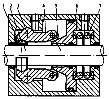
[0008] Such as figure 1 As shown, the braking device of the brake cylinder, the braking device of the brake cylinder, includes a brake shoe 1, a brake shoe seat 2, a rotating shaft 3, a brake arm 4, a pressure wheel 5, a tapered brake piston 6 and Brake spring 7, the brake shoe 1 is installed on the brake shoe seat 2, the brake arm 4 is installed on the rotating shaft 3, the pressure wheel 5 is installed on the bottom of the brake arm 4, and the tapered brake piston 6 is installed on the The movable shoe seat 2 is in contact with the pressure wheel, and the brake spring 7 is installed on the tapered brake piston 6. The braking device of a brake cylinder of the present invention has simple structure and low cost.


PUM


Abstract

The invention discloses a braking device of a braking air cylinder. The braking device of the braking air cylinder comprises a braking shoe, a braking shoe seat, a rotating shaft, a braking arm, a pressing wheel, a conical braking piston and a braking spring. The braking shoe is mounted on the braking shoe seat, the braking arm is mounted on the rotating shaft, the pressing wheel is mounted at the bottom of the braking arm, the conical braking piston is mounted on the braking shoe seat and in contact with the pressing wheel, and the braking spring is mounted on the conical braking piston. The braking device of the braking air cylinder is simple in structure and low in cost.

Description

technical field [0001] The invention relates to a brake device for a brake cylinder. Background technique [0002] In the prior art, the brake device of the cylinder has a complex structure and high cost, cannot meet the needs of use, and occupies a large space. Contents of the invention [0003] The object of the present invention is to provide a brake device for a brake cylinder. [0004] The technical solution adopted by the present invention to achieve the above object is: a braking device for a brake cylinder, including a brake shoe, a brake shoe seat, a rotating shaft, a brake arm, a pressure wheel, a tapered brake piston and a brake spring, the brake shoe is installed on the brake shoe seat, the brake arm is installed on the rotating shaft, the pressure wheel is installed at the bottom of the brake arm, the conical brake piston is installed on the brake shoe seat and contacts the pressure wheel, and the The moving spring is mounted on the conical brake piston. ...

Claims


Application Information

Patent Timeline
IPC IPC(8): F16D49/00F16D65/14F16D121/04
Inventor 李新栋
Owner DALIAN QIANBAO CAST IRON FOUNDRY
Why Eureka
Eureka Blog
Learn More