
Gas stove

A gas stove and gas source technology, which is applied in the combustion method, combustion control, and fuel supply adjustment, etc., can solve the problems of small firepower, insufficient flow curve changes, and insignificant changes in firepower, etc., to increase the effective stroke and convenience. Precisely control the effect of firepower

Active Publication Date: 2014-06-18
BSH ELECTRICAL APPLIANCES JIANGSU +1
View PDF9 Cites 5 Cited by
  • Summary
  • Abstract
  • Description
  • Claims
  • Application Information

AI Technical Summary

Problems solved by technology

As described in the background technology of Chinese utility model patent CN201262248Y, when using the on-off valve of the existing gas stove to adjust the gas, when it is at the maximum firepower, it rotates at a large angle at the beginning, and the firepower does not change. Obviously, in the later stage, the firepower will decrease sharply if only slightly rotated in the later stage, which makes it difficult for users to control the firepower adjustment of the gas stove
[0003] The Chinese utility model patent CN201262248Y improves the spool structure of the on-off valve in an attempt to solve the above problems. This patent makes the air outlet and the air-inducing groove on the spool have irregular curved sections to overcome the existing switch The disadvantage that the flow curve of the valve is not smooth enough when adjusting the flow rate, but in practical applications, this structure does not control the flow rate precisely enough, and the control effect on that section of the flow rate that changes too fast (165° to 185°) during the adjustment process not obvious

Method used


Image

  • Gas stove
  • Gas stove
  • Gas stove

Examples


Embodiment Construction

[0031] In order to have a further understanding of the purpose, structure, features, and functions of the present invention, the following detailed descriptions are provided in conjunction with the embodiments.

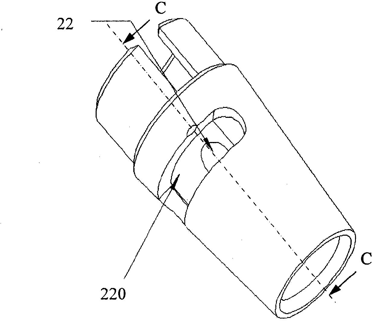
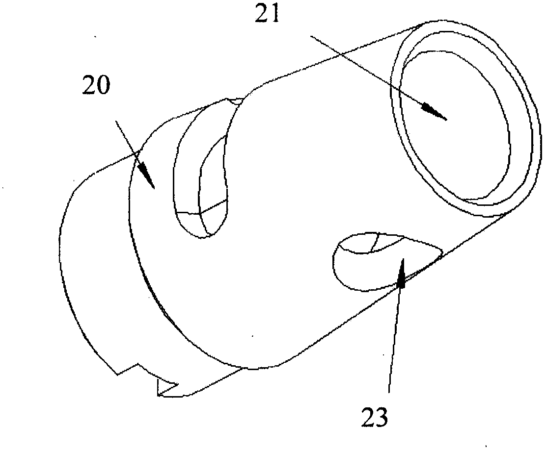
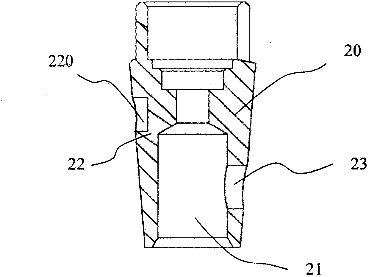
[0032] Please refer to Figure 1 to Figure 19 , The gas stove of the present invention includes an on-off valve 1. The on-off valve 1 includes a valve body 10 and a valve core 20 rotatably arranged in the valve body 1. The valve core 20 is provided with an air inlet passage 21 communicating with an air source. The inner ring fire vent 22 and the outer ring fire vent 23. The valve body 10 is provided with an inner ring main air outlet channel 12 and an inner ring fine adjustment channel 120 corresponding to the inner ring fire air outlet 22, and the valve body 10 is provided with an outer ring main air outlet channel 13 and an outer ring fine adjustment channel 130 corresponding to the outer ring fire air outlet 23. The burner of the gas stove of the present invention in...


PUM


Abstract

The invention relates to a gas stove. The gas stove comprises a switch valve, wherein the switch valve comprises a valve body and a valve element rotatably arranged inside the valve body; the valve element is internally provided with an air inlet passage communicated with an air source; an inner ring fire air outlet hole and an outer ring fire air outlet hole penetrating through the side wall are formed in the side wall of the valve element, wherein the valve body, corresponding to the inner ring fire air outlet hole, is provided with an inner ring main air outlet passage and an inner ring fine tuning passage, and the valve body, corresponding to the outer ring fire air outlet hole, is provided with an outer ring main air outlet passage and an outer ring fine tuning passage. During the process of adjusting heat power, after the outer ring main air outlet passage and the outer ring fire air outlet hole are staggered, the outer ring fine tuning passage supplies gas continuously in a certain angle rotation range; after the inner ring main air outlet passage and the inner ring fire air outlet hole are staggered, the inner ring fine tuning passage supplies gas continuously, so that the whole gas flow control curve becomes more gentle, and the heat power of the gas stove is convenient for a user to control accurately.

Description

Technical field [0001] The present invention relates to a gas stove, in particular to an on-off valve of the gas stove. Background technique [0002] The on-off valve of the existing gas stove usually includes a valve body and a valve core. A tapered hole is opened in the valve body, and the valve core is rotatably assembled in the tapered hole of the valve body. The valve core is provided with an air inlet channel and an air outlet communicating with the air source. When in use, the user rotates the knob of the gas stove to drive the valve core to rotate to adjust the gas flow rate, thereby adjusting the firepower of the gas stove. As described in the background art of the Chinese utility model patent CN201262248Y, when the on-off valve of the existing gas stove is used to adjust the gas, the firepower changes from the point of maximum firepower to a large angle at the beginning, and the firepower does not change. Obviously, in the later stage, if it only rotates slightly, the...

Claims


Application Information

Patent Timeline
IPC IPC(8): F16K27/06F16K5/10F16K5/02
CPCF23N1/007F23N2035/24F16K5/0207F16K5/103F16K27/062F23N2235/24
Inventor 雷东多·何塞刘申昌张伟国
Owner BSH ELECTRICAL APPLIANCES JIANGSU
Learn More