
Ball screw pair failure testing experiment table

A ball screw pair and fault testing technology, which is applied in the testing of mechanical parts, machine/structural parts testing, measuring devices, etc., can solve the problem of weakening the vibration signal of the ball screw pair, and achieve the effect of simple operation

Inactive Publication Date: 2014-06-18
SOUTHEAST UNIV
View PDF5 Cites 4 Cited by
  • Summary
  • Abstract
  • Description
  • Claims
  • Application Information

AI Technical Summary

Problems solved by technology

Chinese invention patents with patent numbers 201010039688.6 and 201010101178.7 disclose the axial loading structure of the ball screw pair, but because it uses a hydraulic system to provide axial force, the piston rod is fixedly connected to the ball nut, which greatly weakens the vibration of the ball screw pair Signal

Method used


Image

  • Ball screw pair failure testing experiment table
  • Ball screw pair failure testing experiment table
  • Ball screw pair failure testing experiment table

Examples


Embodiment Construction

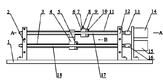
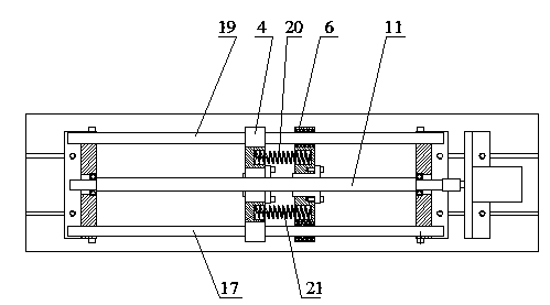
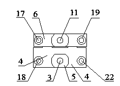
[0018] refer to figure 1 , 2 , 3 and 4, the ball screw pair failure test bench of the present invention includes: a machine base 1, a first support seat 2 and a second support seat 12 are arranged on the machine base 1, and a standard ball nut is provided between the two The supporting seat 4 and the ball nut supporting seat 6 to be tested; the first guide rail sliding hole 28, the second guiding rail sliding hole 30 and the first guiding rail sliding hole 28 and the second guiding rail sliding hole 30 are arranged on the standard ball nut supporting seat 4 The standard ball nut mounting holes 29 between them are respectively provided with the first guide rail 18 and the second guide rail 22 in the slide holes of the two guide rails, and the two ends of the two guide rails are respectively connected with the first support seat 2 and the second support seat 12, The standard ball nut mounting hole 29 is provided with a standard ball nut 5, the internal thread of the standard ba...


PUM


Abstract

A ball screw pair failure testing experiment table comprises an experiment table machine base, two supporting bases are arranged on the machine base, a standard ball nut supporting base and a to-be-tested ball nut supporting base are arranged between the two supporting bases, the ball nut supporting bases are respectively provided with two guide rail sliding holes and a ball nut mounting hole, guide rails are arranged in the guide rail sliding holes respectively, two ends of the guide rails are connected with the two supporting bases respectively, a standard ball nut is arranged in the standard ball nut mounting hole, two protrusions are arranged on the standard ball nut supporting base, the to-be-tested ball nut mounting hole is used for allowing a to-be-tested ball nut to be mounted, the two ball nuts are respectively in threaded connection with a ball screw, two springs are arranged between the two ball nut supporting bases, two ends of the two springs are connected with the standard ball nut supporting base and the to-be-tested ball nut supporting base respectively, two motors are arranged on the machine base and drive the two ball screws to rotate, and the two nut supporting bases move linearly.

Description

technical field [0001] The invention relates to a loaded ball screw pair failure test test bench. Background technique [0002] The fault of the ball screw pair will seriously affect the axial positioning of the CNC machine tool. At present, the research on the performance of the ball screw pair is relatively comprehensive in China, but the research on the fault of the ball screw pair is insufficient. Aiming at the deficiencies in the design of the fault experiment of the ball screw pair, a ball screw fault test bench is designed to facilitate the collection of fault vibration signals. [0003] In order to test the vibration signal of the ball screw pair under the action of axial force, an axial load is applied to the ball screw pair. Chinese invention patents with patent numbers 201010039688.6 and 201010101178.7 disclose the axial loading structure of the ball screw pair, but because it uses a hydraulic system to provide axial force, the piston rod is fixedly c...

Claims


Application Information

Patent Timeline
IPC IPC(8): G01M13/00
Inventor 胡建中张子锋
Owner SOUTHEAST UNIV
Learn More