High temperature and pressure synchronous application method

A pressure and high temperature technology, applied in the field of simultaneous application of high temperature pressure, can solve the problems of test material damage, uneven pressure distribution, damage, etc., and achieve the effect of uniform force load and small transmission loss

Active Publication Date: 2014-06-18
CHINA AIRPLANT STRENGTH RES INST
View PDF5 Cites 3 Cited by
  • Summary
  • Abstract
  • Description
  • Claims
  • Application Information

AI Technical Summary

Problems solved by technology

Uneven loading of the loading mechanism, deformation of the metal plate at high temperature or deformation of the test material will cause uneven pressure distribution on the surfa

Method used


Image

  • High temperature and pressure synchronous application method

Examples


Example Embodiment

Specific embodiment

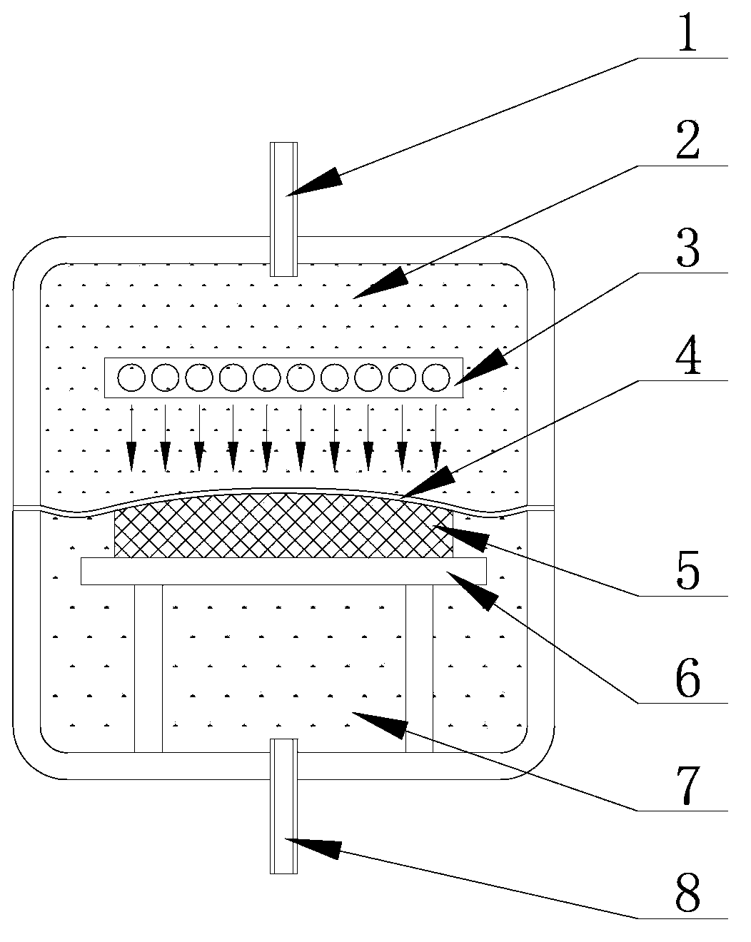
[0025] 1) Prepare a temperature-resistant pressure vessel with a movable partition [4] inside the temperature-resistant pressure vessel, which can divide its cavity into two independent parts, cavity one [2] and cavity two [7], cavity one [ 2] The inner wall is reserved with heater mounting seat and air pressure regulating port [1]; cavity one [2] is reserved on the inner wall with the mounting seat of the test piece installation platform [6] and the air pressure regulating port [8]; The partition [4] is made of metal foil;

[0026] 2) Prepare an adjustable height test piece installation platform [6] and heater [3];

[0027] 3) Open the temperature-resistant pressure vessel and take out the movable partition [4]; fix the test piece [5] and the test piece installation platform [6] in the cavity two [7], adjust the installation position of the test piece [5] to make The loading surface of the test piece [5] protrudes by 0mm~20mm than the mounting surface of the ...


PUM


Abstract

The invention relates to a high temperature and pressure synchronous application method, and belongs to the structural heat intensity test field. A metal foil is adopted to substitute a metal plate, the gas pressure substitutes the metal plate to disperse the intensively-loaded pressure load in order to improve present high temperature-pressure synchronous application method, so the simulation precision of a temperature field and a pressure load is improved, and the raid synchronous coupling application of the temperature and the pressure is realized.

Description

technical field [0001] The invention relates to a method for synchronously applying high-temperature pressure, which belongs to the field of structural thermal strength tests. Background technique [0002] Because the thermal insulation performance of thermal insulation materials is affected by temperature and surface pressure, the change law is nonlinear, and the error of curve extrapolation is large, so the thermal insulation performance test requires testing under temperature and pressure environments. The current general test method is: [0003] Select 200mm × 200mm or 300mm × 300mm standard test material plate test piece, use quartz lamp to heat, use pressure beam or push rod to load the mechanism to increase the load. In order to distribute the heat and force load evenly on the surface of the test piece, the test usually uses a metal plate with a thickness of about 5mm placed on its loaded surface as a uniform heat and uniform load plate. But this kind of test device...

Claims


Application Information

Patent Timeline
IPC IPC(8): G01N25/00
Inventor 王琦秦强王光周刘宁夫吴敬涛
Owner CHINA AIRPLANT STRENGTH RES INST
Why Eureka
Try Eureka