
Eureka
For R&D, Eureka makes reading and utilizing patents & technical documents easy.
Eureka AIR
Designed for self-driven R&D workflows. Generate viable solutions, solve complex R&D challenges, empower your innovation with AI.

Eureka Materials
Designed for material experts only. Revolutionize your material R&D, from search, analyze, to developing new materials.

TechResearch
Generate reliable direction feasibility study reports for your R&D in just a few steps.

TechSeek
Discover and master advanced knowledge NOW. Basics, ideas, possibilities, all at once.

TechMind
As an expert in R&D Theories, TechMind can generates customized viable solutions instantly.

TechRisk
Analyze your overall solution with one click, know your potential R&D risks in advance.

TechMonitor
Get weekly tech updates, stay abreast of the latest tech innovations and key insights.
Device for recovering solar energy
A technology of solar energy and solar cells, applied in the direction of solar thermal energy, solar thermal power generation, solar collectors, etc., can solve the problems of no protection and corrosion of the transmission device, and achieve the effects of material saving, wind load reduction and small stability
- Summary
- Abstract
- Description
- Claims
- Application Information
AI Technical Summary
Problems solved by technology
Method used
Image

Examples
Embodiment Construction
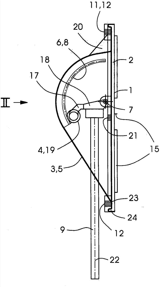
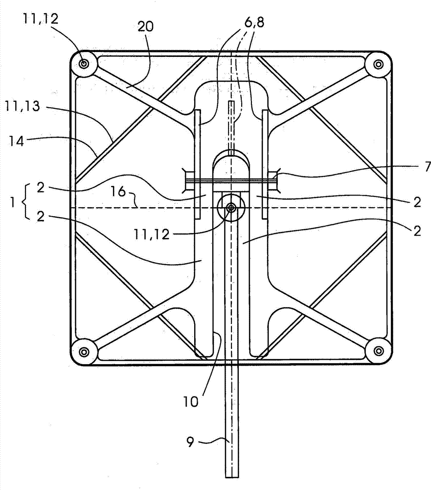
[0019] figure 1 with figure 2 A device for harvesting solar energy is shown. This device is used in solar tower plants to reflect sunlight onto a central absorber or receiver at the top of the tower. A solar tower plant may contain hundreds or thousands of such heliostats, so the low-cost manufacturability of the inventive device is particularly advantageous.
[0020] The device comprises a column 9 (frame) on which a drive unit is arranged, comprising a motor drive 17 for elevational movements as well as a transmission 4 and a motor drive 18 for azimuth movements. The drive 17 pivots the carrier 3 together with the receiving device 1 about an elevation hinge with a horizontal axis 7 . The drive 18 oscillates the carrier 3 together with the receiving device 1 about an azimuthal hinge having a vertical axis 22 coaxial to the tubular support 9 . The carrier 3 forms a capsule 5 which serves as a cover for the entire drive unit including the drives 17 , 18 and the transmissio...
PUM
 Abstract
Description
Claims
Application Information
 - R&D Engineer
- R&D Manager
- IP Professional
- Industry Leading Data Capabilities
- Powerful AI technology
- Patent DNA Extraction
Browse by: Latest US Patents, China's latest patents, Technical Efficacy Thesaurus, Application Domain, Technology Topic, Popular Technical Reports.
© 2024 PatSnap. All rights reserved.Legal|Privacy policy|Modern Slavery Act Transparency Statement|Sitemap|About US| Contact US: help@patsnap.com