Eureka AIR delivers breakthrough ideas for toughest innovation challenges, trusted by R&D personnel around the world.

Primary equipment interval-based oscillograph networking fault analysis system

A technology for primary equipment and fault analysis, applied to electrical components, circuit devices, etc., can solve problems such as prolonging fault processing time and increasing workload of dispatchers

Active Publication Date: 2014-06-18
NANJING TENGEN FUTURE AUTOMATION
View PDF1 Cites 0 Cited by
  • Summary
  • Abstract
  • Description
  • Claims
  • Application Information

AI Technical Summary

Problems solved by technology

In the opened fault waveform, it is necessary to select the channel related to the fault from hundreds of channels in order to conduct fault analysis, which virtually increases the workload of dispatchers and prolongs the fault processing time

Method used


Image

  • Primary equipment interval-based oscillograph networking fault analysis system
  • Primary equipment interval-based oscillograph networking fault analysis system

Examples


Embodiment 1

[0096] When the primary equipment is an AC line, its analog quantity includes 8 analog quantity channels of ABCN phase voltage and current; Dynamic action", "distance action", "long jump receiving", "long jump sending", "high frequency receiving", "high frequency sending", "other switching value"; two sets of switch protection "jump A" , "jump B", "jump C", "total trip", "failure action", "reclosing action", "other switching values"; and three-phase auxiliary nodes of two sets of switches. The format of the model file is as follows:

[0097]

[0098]

[0099] 5305

[0100] 500000

[0101] 100

[0102] 4000

[0103] 1

[0104] 129.74

[0105] 3.205

[0106] 17.74

[0107] 121.87

[0108] 36.59

[0109] 1.118

[0110] 1.764

[0111]

[0112]

[0113]

[0114] 5

[0115] 6

...

Embodiment 2

[0168] When the transformer in the primary equipment room, the analog quantity mainly includes the voltage and current of the high, middle and low sides and the neutral three-phase current. side distance action", "low-voltage side over-current action", "neutral point zero-current action", "heavy gas action", "pressure release action", "other switching value"; ", "jump B", "jump C", "total trip", "failure action", "other switching values"; three-phase switch auxiliary nodes on the high, medium and low sides. Its model file format is as follows:

[0169]

[0170]

[0171]

[0172] 9

[0173] 10

[0174] 11

[0175] 12

[0176]

[0177]

[0178]

[0179]

[0180]

[0181]

[0182]

[0183]

[0184] 25

[0185] 26

[0186] ...

Embodiment 3

[0250] When the primary device is a busbar, its analog value includes ABCN phase voltage and current of each string, and the switch value includes three-phase trip signals of two sets of busbar protection, "bus differential action signal", "bus differential failure joint trip", "other Signal", "jump A", "jump B", "jump C", "total trip", "failure action", "other signals" of each string of switch protection, and the auxiliary node signal of each string of switches, its model file The format is as follows:

[0251]

[0252]

[0253]

[0254]

[0255]

[0256]

[0257]

[0258] 35

[0259] 36

[0260] 37

[0261]

[0262] 32

[0263] 33

[0264] 34

[0265]

[0266] 38

[0267] 39

[0268] 40

[0269]

[0270] ...


PUM


Abstract

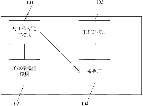
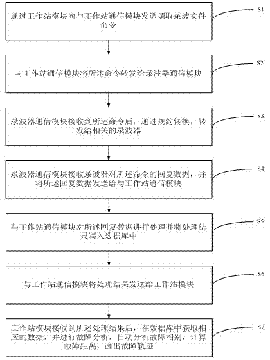
A primary equipment interval-based oscillograph networking fault analysis system comprises a work station communication module for communication with a work station, an oscillograph communication module for communication with an oscillograph, a work station module for analyzing an oscillograph networking fault, and a database for storing oscillograph data, wherein the oscillograph data comprises an oscillograph and primary equipment relation table for describing the relation between primary equipment and the oscillograph and the definition of each channel in an oscillograph wave file. The system only shows the waveform of the primary equipment to a scheduling person and can be used for automatically analyzing fault phase, calculating fault distance and drawing a fault track according to parameters of the primary equipment, so that the aims of helping the scheduling person to quickly take a fault waveform, accurately perform fault analysis, rapidly recover from the fault and ensure the safe and stable operation of a power system are achieved.

Description

technical field [0001] The invention relates to the field of power grid fault analysis, in particular to a fault analysis system for wave recorder networking based on primary equipment intervals. Background technique [0002] At present, most provincial and municipal power grid dispatching centers have a set of wave recorder networking system, which can complete the access of all wave recorders in the area, and the system can correctly retrieve the fault waveform in the fault recorder, And use common waveform analysis tools to view waveforms. [0003] However, the system is based on the wave recorder. The current wave recorder can realize the access of 64 analog quantities and 128 switch quantities, and even more can access 128 analog quantities and 256 switch quantities. Therefore, a wave recorder in a substation is often connected to multiple analog and switch quantities of primary equipment intervals, among which the switch quantities are more complex, and the switch qua...

Claims


Application Information

Patent Timeline
IPC IPC(8): H02J13/00
Inventor 彭鹏汪永军
Owner NANJING TENGEN FUTURE AUTOMATION
Why Eureka
Eureka Blog
Learn More