Motor

A casing and box cover technology, which is applied to electrical components, electromechanical devices, electric components, etc., can solve the problems of poor production process, not easy to operate, and difficult to realize, and achieves good heat dissipation effect, simple structure, and is conducive to cooling effect

Active Publication Date: 2014-06-18
ZHONGSHAN BROAD OCEAN
View PDF5 Cites 8 Cited by
  • Summary
  • Abstract
  • Description
  • Claims
  • Application Information

AI Technical Summary

Problems solved by technology

[0002] The traditional motor structure includes the shaft, rotor assembly, stator core, stator winding, end insulation, casing, front end cover, rear end cover and circuit board. The shaft is connected with the rotor assembly, and the stator core is sleeved outside the rotor assembly. , the end insulation is installed on the end face of the stator core, the stator winding is wound on the stator core, the stator core and the casing are connected together, the front end cover and the rear end cover are installed at both ends of the casing, and the rotating shaft is supported on the front end cover and the casing. On the bearing of the rear end cover, the circuit board is mainly fixed on the end insulation, and the insert piece is protruded from the end insulation, inserted into the socket on the circuit board, and then welded on the circuit board. The other is the stator three-phase Connect the connector with a wire, and then insert it into the connector on the circuit board. These two solutions are not easy to operate, and the cost is high. In addition, it is difficult to realize when the internal space of the motor is small, and the production process is not good.

Method used


Image

  • Motor
  • Motor
  • Motor

Examples


Embodiment 1

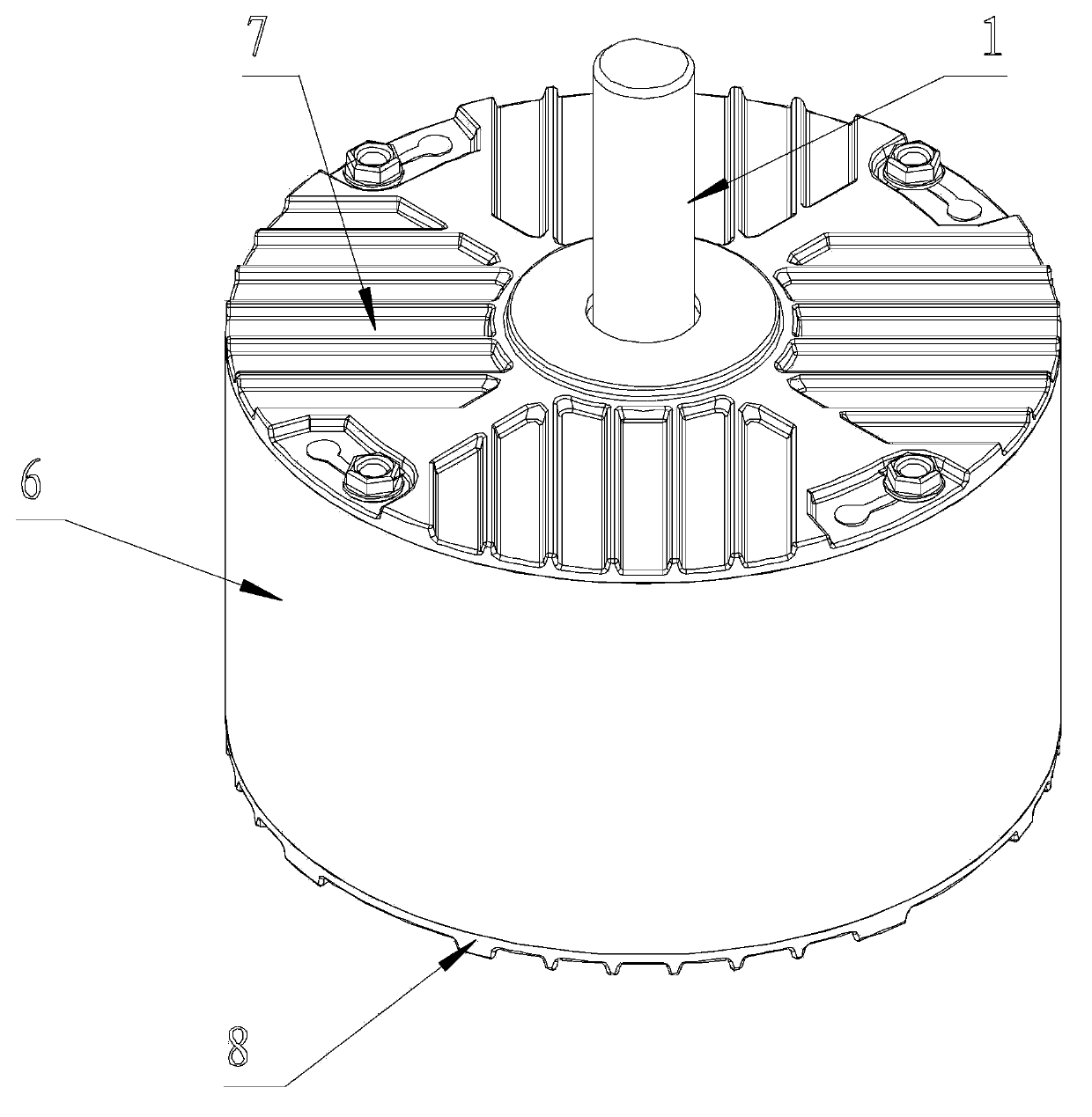
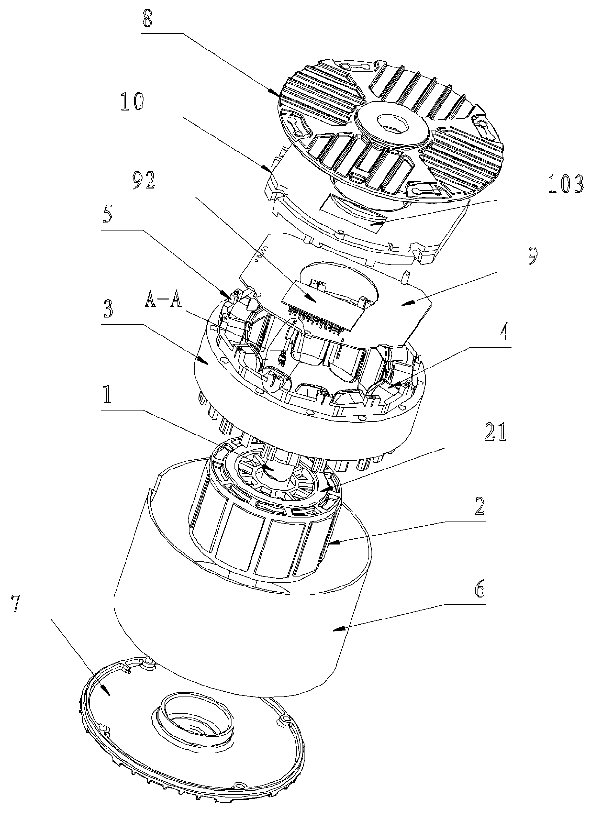
[0023] Embodiment one: if Figure 1 to Figure 6 As shown, the present invention is a motor, including a rotating shaft 1, a rotor assembly 2, a stator core 3, a stator winding 4, end insulation 5, a casing 6, a front end cover 7, a rear end cover 8, a circuit board 9 and a box The cover 10, the rotating shaft 1 and the rotor assembly 2 are connected together, the stator core 3 is set outside the rotor assembly 2, the end insulation 5 is installed on the end face of the stator core 3, the stator winding 4 is wound on the stator core 3, and the stator iron core The core 3 and the casing 6 are connected together, the front end cover 7 and the rear end cover 8 are installed at both ends of the casing 6, the rotating shaft 1 is supported on the bearings of the front end cover 7 and the rear end cover 8, and the box cover 10 is installed on the rear end cover 8 On the inner bottom surface, the circuit board 9 is installed in the box cover 10, and it also includes a connecting wire c...

Embodiment 2

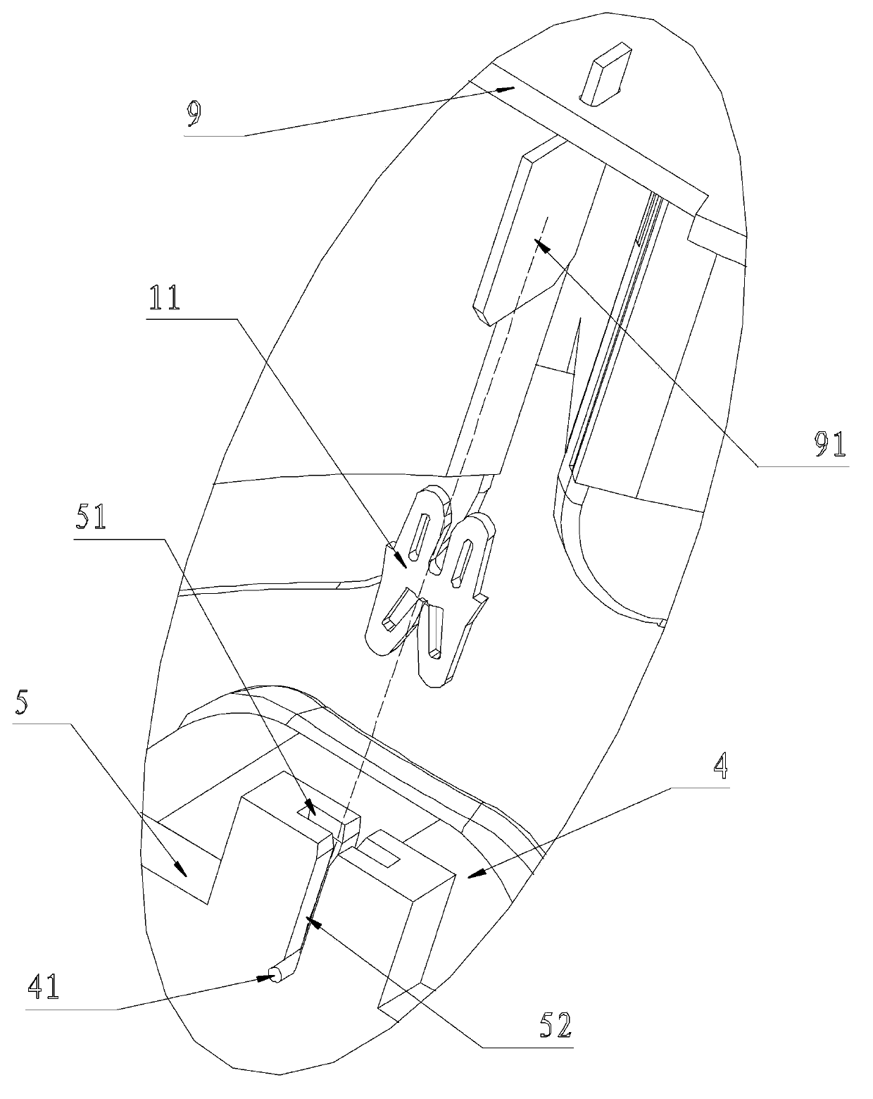
[0024] Embodiment 2: On the basis of Embodiment 1, the following technical features are added: a groove 51 is opened on the end insulation 5, a gap 52 is provided in the middle of the groove 51 and on the end insulation 5, and the gap 52 communicates with the groove 51 , the wire end 41 of the stator winding 4 is embedded in the gap 52, the connecting wire clip 11 is clamped in the groove 51 and the tail of the connecting wire clip 11 clamps the wire end 41 of the stator winding 4, and the tail of the insert piece 91 is inserted into the gap 52 and is connected by the wire Clamp 11 ends are clamped.

Embodiment 3

[0025] Embodiment 3: On the basis of Embodiment 1 or Embodiment 2, the following technical features are added: the insertion piece 91 is welded on the circuit board 9 .


PUM


Abstract

The invention discloses a motor. The motor comprises a rotating shaft, a rotor assembly, a stator core, a stator winding, an end insulation piece, a casing, a front end cover, a rear end cover, a circuit board and a box cover, wherein the rotating shaft is connected with the rotor assembly, the stator core is sleeved on the rotor assembly, the end insulation piece is installed at an end surface of the stator core, the stator winding is wound on the stator core, the stator core is connected with the casing; the front end cover and the rear end cover are arranged at two ends of the casing, the rotating shaft is supported on bearings of the front end cover and the rear end cover, the box cover is installed on an internal side bottom surface of the rear end cover, and the circuit board is arranged in the box cover. The motor further comprises a connecting wire clamp; the connecting wire clamp is installed on the end insulation piece; and one end of the connecting wire clamp is electrically connected with a wire end of the stator winding, and the other end of the connecting wire clamp is electrically connected with an insertion sheet on the circuit board. The motor is advantageous in structural simplicity, easiness in assembly, low cost and excellent manufacturability.

Description

Technical field: [0001] The invention relates to an electric machine. Background technique : [0002] The traditional motor structure includes the shaft, rotor assembly, stator core, stator winding, end insulation, casing, front end cover, rear end cover and circuit board. The shaft is connected with the rotor assembly, and the stator core is sleeved outside the rotor assembly. , the end insulation is installed on the end face of the stator core, the stator winding is wound on the stator core, the stator core and the casing are connected together, the front end cover and the rear end cover are installed at both ends of the casing, and the rotating shaft is supported on the front end cover and the casing. On the bearing of the rear end cover, the circuit board is mainly fixed on the end insulation, and the insert piece is protruded from the end insulation, inserted into the socket on the circuit board, and then welded on the circuit board. The other is the stator three-phase ...

Claims


Application Information

Patent Timeline
Patent Type & Authority Applications(China)
IPC IPC(8): H02K3/38H02K3/34H02K3/24H02K11/00H02K11/215
Inventor 潘明攀范建明刘骁
Owner ZHONGSHAN BROAD OCEAN
Why Eureka
Try Eureka