Method for manufacturing a stator of an electric machine, stator and electric machine

A stator and rotor technology, used in the field of stators, stators and motors for manufacturing motors, can solve the problems of reducing motor power intensity, high material cost, high scrap rate, etc., to improve concentricity, minimize cost, and improve quality. Effect

Inactive Publication Date: 2018-08-17
ROBERT BOSCH GMBH
View PDF6 Cites 0 Cited by
  • Summary
  • Abstract
  • Description
  • Claims
  • Application Information

AI Technical Summary

Problems solved by technology

This method is very complicated due to the separate steps of: producing the sintered magnet; pre-assembling the sintered magnet in the magnet retaining ring using retaining elements or bonding material; and subsequently securing the magnet retaining ring to the poles. boots and requires high logistical, cost-technical and tool-technical outlays, since the components must be inserted precisely into one another in order to ensure a permanent stability of the stator
Furthermore, the manufacture of sintered magnets by cutting them out of a block leads to higher offcuts and thus higher material costs
Furthermore, fixing the separately manufactured magnets in the likewise prefabricated magnet fixing rings and pushing and fixing the magnet fixing rings in the pole shoes is complicated and difficult due to the many individual components and the lack of dimensional accuracy of the fixing elements, so that the work involves high scrap rate
Furthermore, due to the complex structure in design, air gaps are created between the magnets and those parts of the stator on which they are fastened, which air gaps reduce the power density of the motor thus formed

Method used


Image

  • Method for manufacturing a stator of an electric machine, stator and electric machine
  • Method for manufacturing a stator of an electric machine, stator and electric machine
  • Method for manufacturing a stator of an electric machine, stator and electric machine

Examples


Embodiment Construction

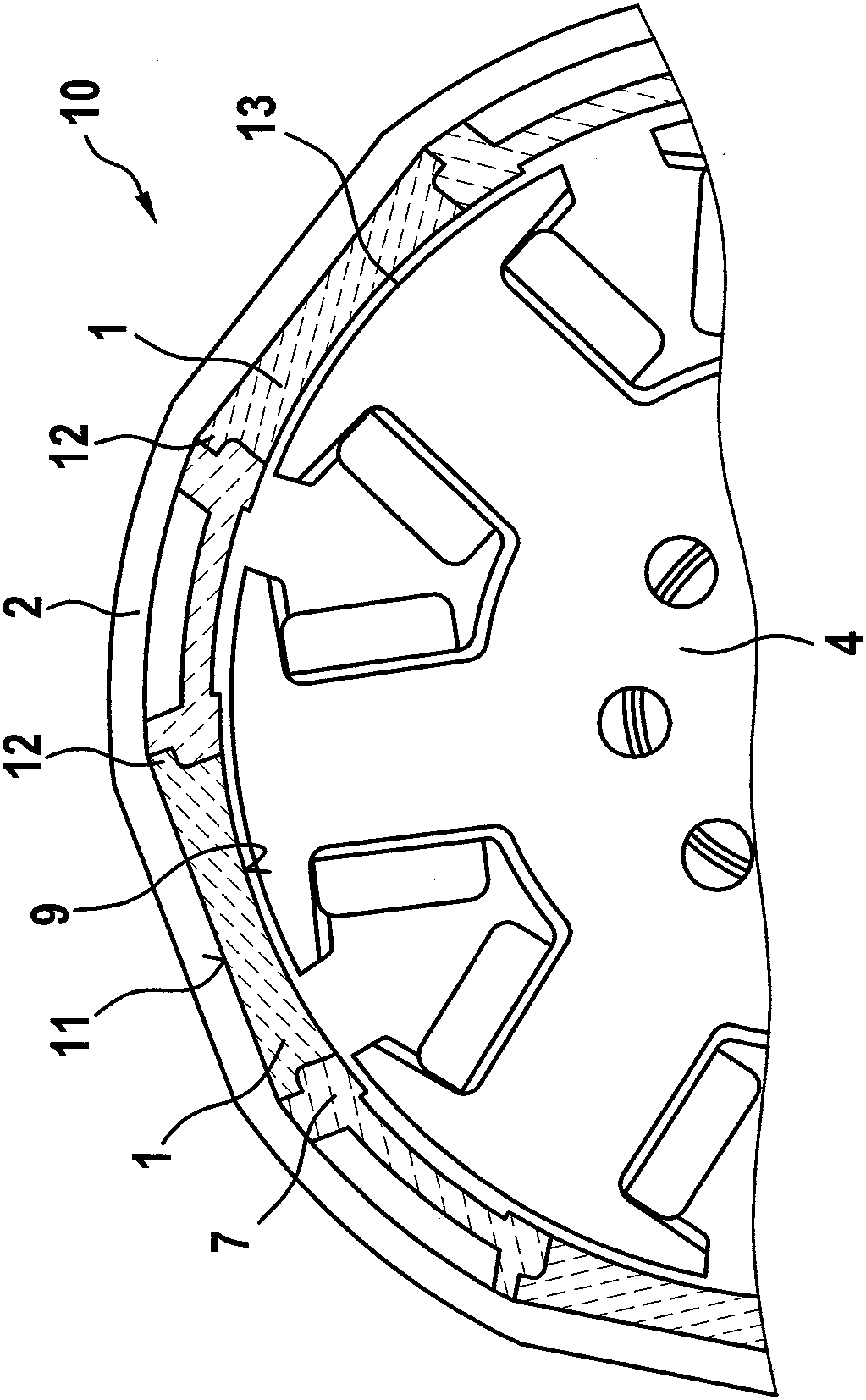
[0030] figure 1It is a schematic plan view of an electric machine 10 according to a first advantageous development of the invention. The electric machine 10 comprises four magnetic elements 1, 1a and a pole piece 2, wherein the magnetic elements 1, 1a are injected directly into the pole piece 2 by means of injection molding, whereby a The material fits the connection. The letters "S" and "N" designate the respective polarity of the member. There is no air gap between the magnetic elements 1 , 1 a and the pole piece 2 , so that the magnetic flux is uniform and the power density of the electric machine 10 is very good. Furthermore, the pole piece has two undercuts 3 , by means of which a form-fit connection is formed between the magnetic element 1 a and the pole piece 2 , which improves the positioning of the magnetic element 1 a on the pole piece 2 . This has a positive effect on the mechanical stability of the motor 10 . Furthermore, the electric machine 10 also includes a...


PUM


Abstract

The invention relates to a method for manufacturing a stator of an electrical machine, particularly an electrical motor. The method comprises the following steps: at least a magnetic element (1, 1a) is injected and moulded onto at least a component of the stator (8), and the magnetic element (1, 1a) is fixed to at least a component of the stator (8).

Description

technical field [0001] The invention relates to a method for producing an electric machine and in particular a stator of an electric machine, a stator and an electric machine. Background technique [0002] A stator for an electrical machine generally comprises individual components, namely a pole piece, a magnet retaining ring and sintered magnets. Such stators have previously been produced by manufacturing a plurality of sintered magnets in a first process by cutting out the elements from a block made of magnetic material, and fixing the sintered magnets in a second process, i.e. pre-assembled Fitted onto the magnet retaining ring, and then in a third process step the magnet structural unit formed in this way consisting of the magnet and the magnet retaining ring is inserted into the pole piece. This method is very complicated due to the separate steps of: producing the sintered magnet; pre-assembling the sintered magnet in the magnet retaining ring using retaining element...

Claims


Application Information

Patent Timeline
Patent Type & Authority Patents(China)
IPC IPC(8): H02K15/03H02K1/17
CPCH02K1/17H02K15/03
Inventor P.伯纳德U.吕特克D.克卢姆普J.盖斯勒
Owner ROBERT BOSCH GMBH
Why Eureka
Try Eureka