No-magnetic-resistance type direct current generator

A DC generator and reluctance technology, applied in DC commutators, electrical components, electromechanical devices, etc., can solve the problems of hindering the rotation of the rotor and requiring high power for the rotation of the rotor

Inactive Publication Date: 2014-06-18
包海荣
View PDF6 Cites 0 Cited by
  • Summary
  • Abstract
  • Description
  • Claims
  • Application Information

AI Technical Summary

Problems solved by technology

[0003] In the above two structural forms, both the stator and the rotor are made of magnetically permeable materials, the gap between the stator and the rotor is about 1mm, and the magnetic field generated by the magnetic poles has a certain att...

Method used


Image

  • No-magnetic-resistance type direct current generator
  • No-magnetic-resistance type direct current generator

Examples


Embodiment Construction

[0012] Below by embodiment and in conjunction with accompanying drawing, the present invention will be further described:

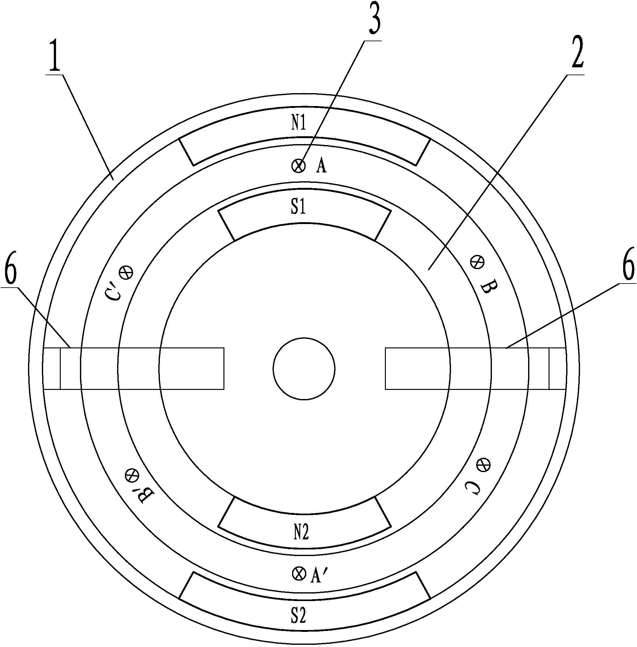
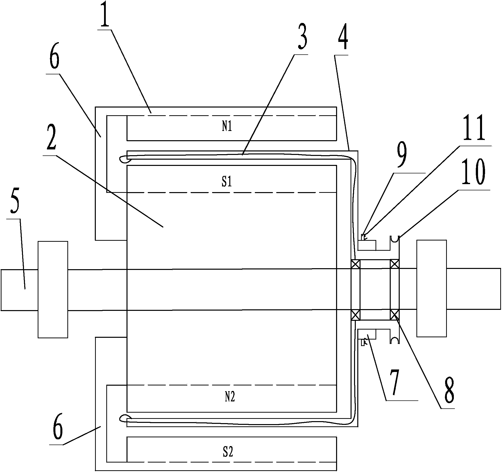
[0013] combine figure 1 —— figure 2 As shown, a non-reluctance DC generator consists of a casing 1, a core 2, a coil 3, a coil carrier 4, a central shaft 5, a connecting arm 6, a commutator 7, a bearing 8, a carbon brush 9, and a coil carrier Belt pulley 10, direct current output conversion switch 11 etc. are formed.

[0014] The casing 1 and the core 2 are annular parts made of magnetically permeable materials, which are the same as those used for stators and rotors in traditional generators, such as silicon steel sheets. The casing 1 is set outside the movement 2, and there is a gap between the inner wall of the casing 1 and the outer wall of the movement 2, usually about 1 cm, so that the coil carrier 4 wrapped with the coil 3 can extend into the gap. The casing 1 and the movement 2 are fixedly connected together by the connecting arm 6, and then f...


PUM


Abstract

The invention discloses a no-magnetic-resistance type direct current generator. A shell (1) and a core (2) are annular pieces made of magnetically conductive materials, are fixedly connected together through a connecting arm (6), and then are fixedly sleeved onto a central shaft (5); a first N magnetic pole and a second S magnetic pole are arranged inside the shell; a first S magnetic pole and a second N magnetic pole are arranged inside the core; a coil (3) is wound around a coil carrier (4) made of a non-magnetically conductive material; an installation part of the coil carrier is fixedly connected with a coil carrier belt wheel (10) into a whole, and then is arranged on the central shaft through a bearing; the other end of the coil carrier stretches into a gap between the shell and the core; the installation part of the coil carrier is provided with a commutator, a carbon brush and a direct current output change-over switch. According to the generator, no-magnetic-resistance type power generation is realized, and higher electric power is obtained by using lower power.

Description

technical field [0001] The invention relates to generators, especially to the technical field of electromagnetic power generation. Background technique [0002] Existing electromagnetic generators, whether they are AC generators, DC generators, or AC / DC generators, are mainly composed of a stator and a rotor. One structural form is that the coil is wound on the stator, and the magnetic poles are arranged on the rotor, and the other structural form is that the coil is wound on the rotor, and the magnetic poles are arranged on the stator. The stator is fixed, the rotor rotates, and the current is generated by cutting the magnetic force lines through the coil. [0003] In the above two structural forms, both the stator and the rotor are made of magnetically permeable materials, the gap between the stator and the rotor is about 1mm, and the magnetic field generated by the magnetic poles has a certain attraction to the carrier (stator or rotor) wound by the coil , thus generati...

Claims


Application Information

Patent Timeline
IPC IPC(8): H02K23/40
Inventor 包海荣
Owner 包海荣
Why Eureka
Try Eureka