Heat-generating inductor for high-frequency soldering station and manufacturing method thereof

A manufacturing method and high-frequency welding technology, which is applied in the manufacture of inductors/transformers/magnets, inductors, fixed inductors, etc., can solve the problems of reduced thermal energy efficiency and easy damage of inductor coils, and achieve the efficiency of converting electrical energy into heat energy Reduce and solve the effect of fragile

Inactive Publication Date: 2015-04-22
文阳洋
View PDF5 Cites 0 Cited by
  • Summary
  • Abstract
  • Description
  • Claims
  • Application Information

AI Technical Summary

Problems solved by technology

[0003] The invention provides a heating inductor for a high-frequency soldering station and a manufacturing method thereof, in order to solve the technical problems that the inductance coil of the heating inductor for a high-frequency soldering station is easily damaged and the efficiency of converting electric energy into heat energy is reduced

Method used


Image

  • Heat-generating inductor for high-frequency soldering station and manufacturing method thereof
  • Heat-generating inductor for high-frequency soldering station and manufacturing method thereof

Examples


Embodiment 1

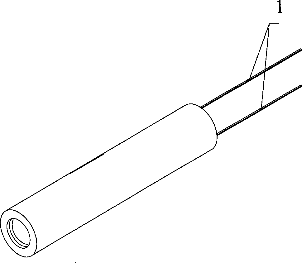
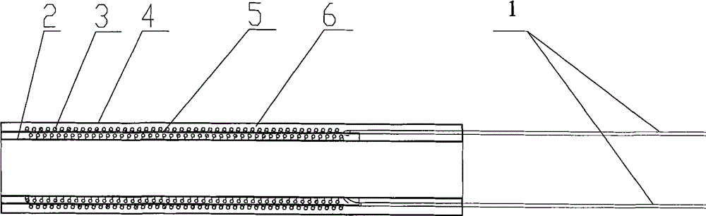
[0023] Such as figure 1 , 2 As shown, a heating inductor for a high-frequency soldering station includes an inner skeleton, an inductance coil wound on the skeleton and connected to an external power line 1, and a bushing sleeved on the periphery of the inductance coil. The inner skeleton is made of ceramic material The finished ceramic inner tube 2, the casing is a ceramic outer tube 4 made of ceramic material, the space between the ceramic inner tube and the ceramic outer tube is filled with a sealed ceramic intermediate layer, the inductance coil is a wound double-layer electromagnetic wire 3, and the double-layer An insulating layer 5 made of high temperature resistant insulating material such as high temperature glass fiber cloth or mica paper is arranged between the electromagnetic wires 3 .

Embodiment 2

[0025] A heating inductor for a high-frequency soldering station and a manufacturing method thereof, comprising the following steps:

[0026] 1. Evenly wind the first layer of magnet wire on the ceramic inner tube to keep a sufficient distance between turns;

[0027] 2. Spread a layer of colloidal ceramic powder on the first wound magnetic wire, and add an insulating layer made of high temperature resistant insulating material, such as high temperature glass fiber cloth or mica paper;

[0028] 3. Use the same magnet wire to wind the second layer of magnet wire evenly outside, so as to keep a sufficient distance between turns;

[0029] 4. Spread a layer of colloidal ceramic powder on the second layer of coil that has been wound, and put on the ceramic outer tube;

[0030] 5. According to the heating characteristics of the ceramic powder used, heat it in a kiln or oven to form a heating inductor for a high-frequency soldering station with an inductance coil inside.

[0031] A....


PUM


Abstract

The invention relates to a heat-generating inductor for a high-frequency soldering station and a manufacturing method thereof. The heat-generating inductor comprises a skeleton arranged at the inner layer, an inductive coil wound around the skeleton and externally connected with a power line and a sleeve sheathed outside the inductive coil, wherein the skeleton arranged at the inner layer is a ceramic inner tube made of insulating ceramic materials, the sleeve is a ceramic outer tube made of insulating ceramic materials, and a sealed insulating ceramic intermediate layer is filled between the ceramic inner tube and the ceramic outer tube. By sealing the inductive coil in the tube wall of the insulating ceramic tube, the invention can ensure favorable coil turn-to-turn insulation and favorable insulation to the inner and outer layers, and can isolate the inductor line from the air to avoid the oxidation of the inductor line. Simultaneously, the sleeve without a metal skeleton can not produce magnetic reluctance, so that the efficiency of conversing electric energy into heat energy is higher.

Description

technical field [0001] The invention relates to a heating inductor for a high-frequency soldering station and a manufacturing method thereof. Background technique [0002] At present, the inductance coil used to generate the high-frequency magnetic field on the known high-frequency soldering station welding pen is to wind the electromagnetic wire with a layer of glass fiber insulation layer on the skeleton made of stainless steel, and the outer layer is covered with a layers of stainless steel tubes. When this structure is working, it is easy to cause inter-turn short circuit and external leakage due to air gap discharge between the turns of the electromagnetic wire and between the electromagnetic wire and the inner and outer stainless steel, which will cause damage to the inductance coil; Generate reluctance, thereby reducing the magnetic field strength of the high-frequency magnetic field generated by the inductance coil acting on the soldering iron head, resulting in a r...

Claims


Application Information

Patent Timeline
Patent Type & Authority Patents(China)
IPC IPC(8): H01F17/00H01F27/30H01F27/28H01F27/32H01F41/00
Inventor 文阳洋
Owner 文阳洋
Why Eureka
Try Eureka