Device and method for controlling a switched reluctance motor

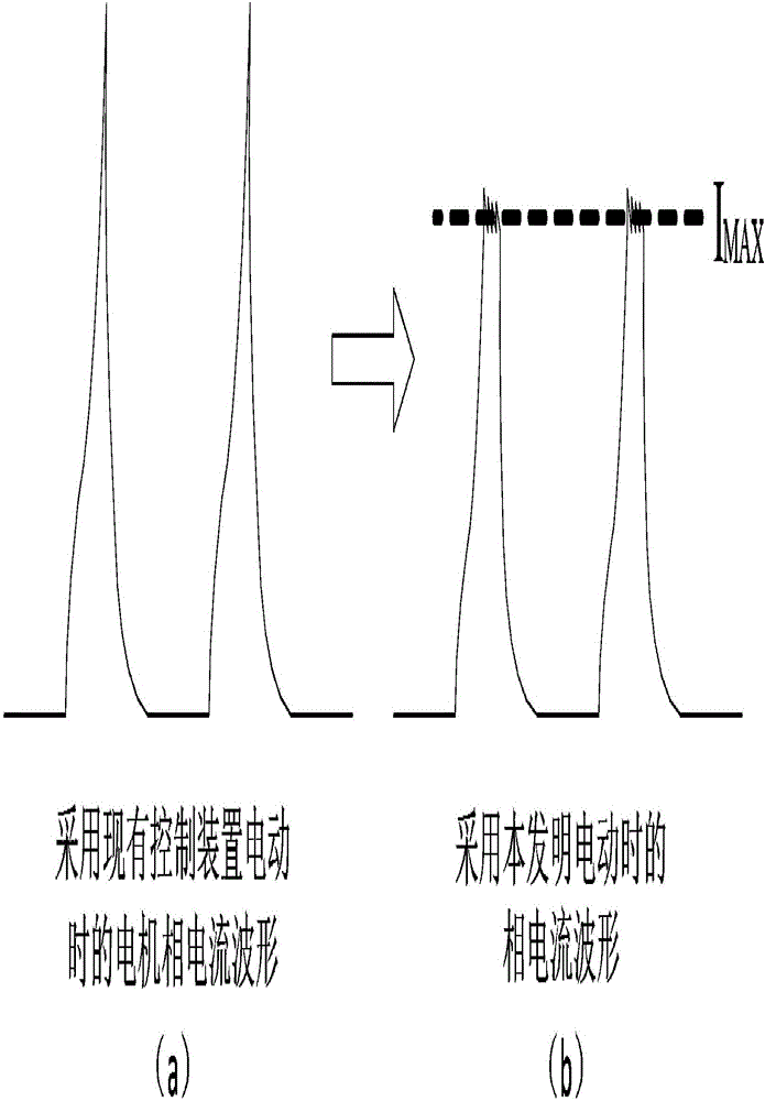
A technology of switched reluctance motors and control devices, applied in the direction of torque ripple control, etc., can solve problems such as difficult to apply and reduce the efficiency of switched reluctance motors, and achieve the effects of suppressing rising speed and peak, eliminating jitter, and suppressing torque ripple Effect

Inactive Publication Date: 2017-03-29
NIDEC BEIJING DRIVE TECH CO LTD
View PDF4 Cites 0 Cited by
  • Summary
  • Abstract
  • Description
  • Claims
  • Application Information

AI Technical Summary

Problems solved by technology

[0006] In the specific speed range of 50% to 75% of the rated speed, the speed is already high. If the current chopping control method is used, the efficiency of the switched reluctance motor will be greatly reduced, and it is difficult to apply

Method used


Image

  • Device and method for controlling a switched reluctance motor
  • Device and method for controlling a switched reluctance motor
  • Device and method for controlling a switched reluctance motor

Examples


Embodiment Construction

[0021] The present invention will be described in detail below in conjunction with the accompanying drawings and embodiments.

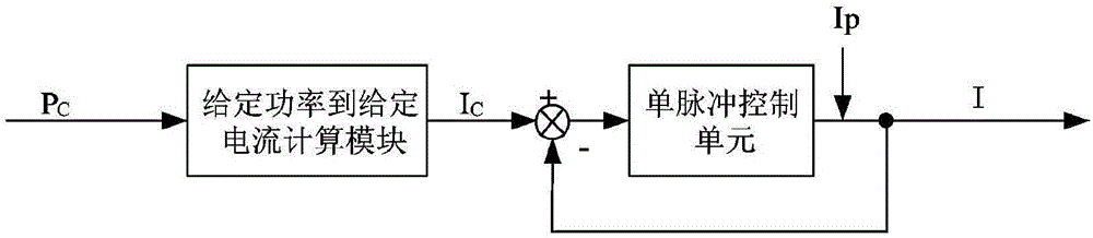
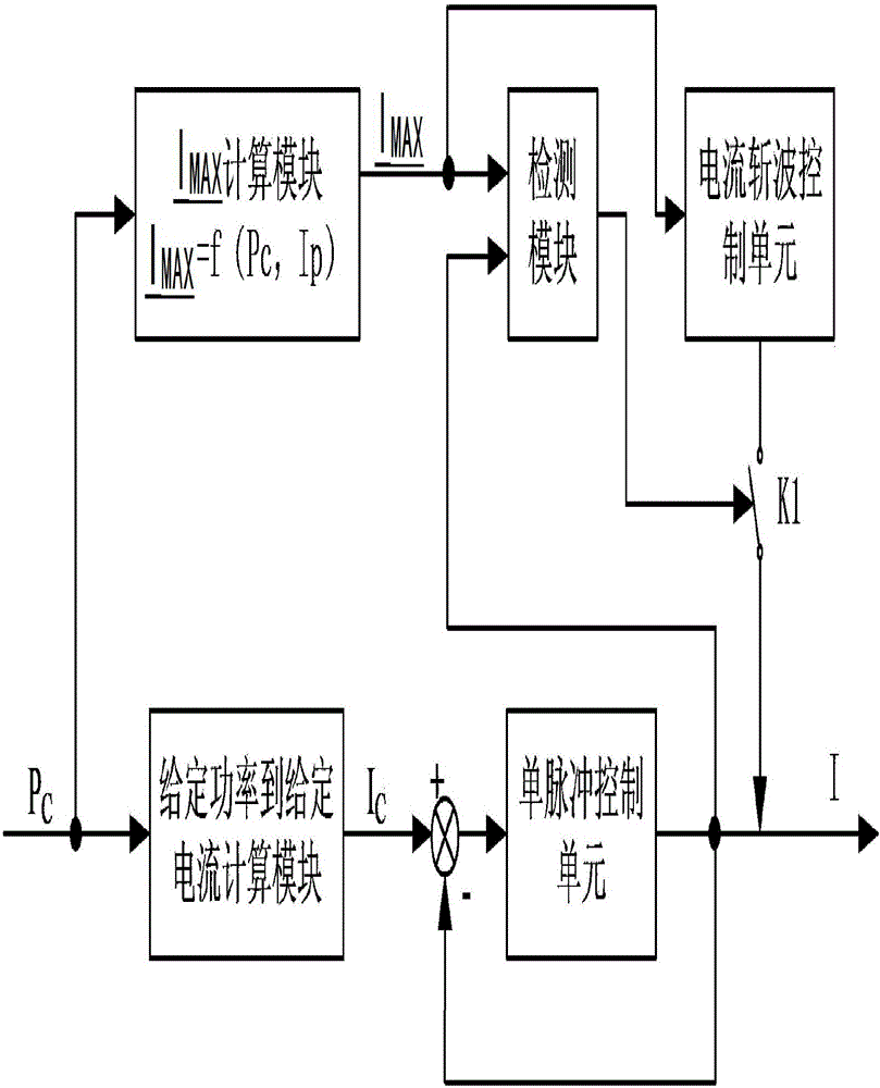
[0022] The invention provides a switched reluctance motor control device. When the switched reluctance motor is in a specific speed range of 50% to 75% of the rated speed, it includes: a single pulse control unit, wherein, when the switched reluctance motor is in the rated speed range 50% to 75% of the specific speed range, the control device also includes: current chopping control unit, I MAX Calculation module, detection module and switch device K1;

[0023] I MAX Calculation module to calculate the maximum limit current I of the current phase current of the single-phase winding of the motor MAX , I MAX is the current given output power P of the switched reluctance motor C and set the lower limit current value I P function as parameter, I MAX =f(P C , I P ); I MAX The calculation module is based on the current given output power P of the mo...


PUM


Abstract

The invention relates to a switch reluctance motor control device and method. When a switch reluctance motor is within the specific revolving speed range of 50-70% of rated revolving speed, the control device comprises a monopulse control unit, a current chopping control unit, an IMAX (image maximum) computation module, a detection module and a switching device K1, wherein the IMAX computation module is used for computing the maximum limiting current IMAX of the monopulse winding phase current of the current motor; the switching device K1 is closed by the detection module when the first current monopulse winding phase current I is bigger than or equal to the maximum limiting current IMAX of the current phase winding phase current, and the current chopping control unit is started to simultaneously carry out monopulse control and current chopping control on the present phase winding phase current; otherwise, the switching device K1 is cut off, and the current phase winding phase current is subjected to monopulse control. The control device and method provided by the invention can be realized by combining a monopulse control mode with a current chopping control mode, the ascending velocity and the peak of the winding phase current can be effectively inhibited, and the shake of an electromechanical coupling device can be inhibited and eliminated.

Description

technical field [0001] The invention relates to a switched reluctance motor control device and method, in particular to the ability to suppress and eliminate the vibration of an electromechanical coupling device based on a switched reluctance motor when the switched reluctance motor is in a specific speed range of 50% to 75% of the rated speed A switched reluctance motor control device and method. Background technique [0002] The switching magneto control methods are mainly current chopping control, voltage chopping control, and single pulse control. Current chopping control is to compare the phase current I with the current chopping limit value I when the rotor position is in the current conduction interval MAX , if I<I MAX , the power switching element is turned on, and the current rises to the chopping limit; if I≥I MAX , the power switching device is turned off and the current drops. During current chopping control, the phase current is directly controlled to mai...

Claims


Application Information

Patent Timeline
Patent Type & Authority Patents(China)
IPC IPC(8): H02P6/10
Inventor 郭晓颖马志国刘德超
Owner NIDEC BEIJING DRIVE TECH CO LTD
Why Eureka
Try Eureka