A control method for a flyback converter

A flyback converter and control method technology, applied in control/regulation systems, conversion of DC power input to DC power output, instruments, etc., can solve the problems of large oscillation and main switch current spikes, etc., to reduce oscillation and alleviate The effect of filtering pressure and improving efficiency

Active Publication Date: 2021-02-23
MORNSUN GUANGZHOU SCI & TECH
View PDF8 Cites 0 Cited by
  • Summary
  • Abstract
  • Description
  • Claims
  • Application Information

AI Technical Summary

Problems solved by technology

[0005] The technical problem to be solved by the present invention is to provide a control method for a flyback converter to solve the problem that the existing active clamp flyback circuit has large oscillation and the main switching tube will generate a large The problem with current spikes

Method used


Image

  • A control method for a flyback converter
  • A control method for a flyback converter
  • A control method for a flyback converter

Examples


Embodiment 1

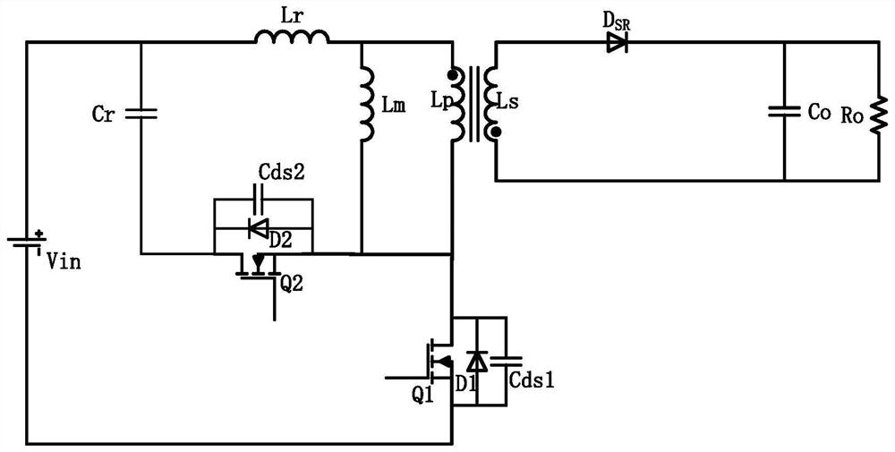
[0056] Such as Figure 4 to Figure 6 As shown, the present invention discloses a control method of a flyback converter, which is suitable for a flyback converter composed of a main power circuit, a clamp circuit and an output filter circuit; the main power circuit is provided with a transformer and a main switch Tube Q1, the clamping circuit is provided with a clamping capacitor Cr and a main clamping tube Q4, the first end of the primary winding Lp of the transformer is used as the positive input terminal VIN+ of the flyback converter, and the primary side The second end of the winding Lp, the drain of the main switching transistor Q1, and the source of the main clamping transistor Q4 are connected, and the drain of the main clamping transistor Q4 is connected to the The positive input terminal VIN+, the source of the main switching tube Q1 is used as the negative input terminal VIN- of the flyback converter; the secondary winding Ls of the transformer is used to output direc...

Embodiment approach

[0108]The level state of the main clamp driving signal Vgs4 in the first period is: it changes in a straight-line rising manner, gradually rising from low level to high level, that is: the main clamp driving signal Vgs4 is at The first period is a triangle wave.

[0109] In addition, the level state of the main clamp driving signal Vgs4 in the first period, in addition to changing in a straight line, can also follow other curves such as arc rise, as long as it can be gradually increased from low level to High level is enough.

Embodiment 3

[0111] On the basis of the above-mentioned embodiment 1 or embodiment 2, this embodiment 3 also adopts the following preferred implementation modes:

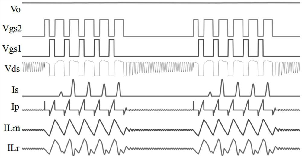
[0112] The ΔT1, ΔT3, ΔT5, ΔT6, and ΔT8 all take the minimum value, that is:

[0113] At the end of the first period, that is, at time t1, the excitation inductance Lm and leakage inductance Lr of the transformer are stored to the minimum energy required to realize the zero-voltage switching of the main switching tube Q1;

[0114] At the end of the third period, that is, at time t3, the voltage of the parasitic capacitance Cds1 of the main switching transistor Q1 drops to zero;

[0115] At the end of the fifth period, that is, at time t5, the drain-source voltage of the main switching transistor Q1 rises to Vin+Vc;

[0116] At the end of the sixth period, that is, at time t6, the secondary current of the transformer is reduced to zero;

[0117] At the end of the eighth period, that is, at time t8, the voltage of the parasitic c...


PUM


Abstract

The invention discloses a control method of a flyback converter. By adding clamping diodes, auxiliary capacitors and auxiliary clamping tubes to the clamping circuit of the flyback converter, and using the main switch drive signal, the main clamp drive signal and the The auxiliary clamp driving signal respectively drives the main switching tube, the main clamping tube and the auxiliary clamping tube, and in the first period, the setting of the main clamping driving signal is gradually increased from low level to high level, so that the flyback conversion The transformer works intermittently according to the alternating cycle of working time and non-working time. During the working time, the three switching tubes are in the intermittent working mode, and all of them can realize zero-voltage switching; moreover, the clamping diode can be used to clamp the transformer , to eliminate oscillation during the second and seventh periods of working time and non-working hours; and, the present invention can prevent the drain-source voltage of the main switching tube from changing abruptly in the first period, avoiding the main switching tube in the prior art. There is a problem with a large current spike when entering the active phase.

Description

technical field [0001] The invention relates to the field of switching converters, in particular to a control method for a flyback converter. Background technique [0002] With the rapid development of power electronics technology, switching converters are used more and more widely, especially people put forward more requirements for switching converters with high power density, high reliability and small size. The flyback topology has the advantages of simple structure and low price, and is widely used in low-power switching converters. However, the common flyback topology is a hard switch and cannot recover leakage inductance energy, thus limiting the efficiency and size of the common flyback topology. In order to seek a breakthrough in the size and efficiency of low-power switching converters, soft switching technology has become a research hotspot in power electronics technology. [0003] At present, the representative of the flyback topology that can realize the soft ...

Claims


Application Information

Patent Timeline
Patent Type & Authority Patents(China)
IPC IPC(8): H02M3/335H02M1/32
CPCH02M1/32H02M3/33569H02M1/0038H02M1/0058Y02B70/10
Inventor 尹向阳钟天明马守栋王志燊
Owner MORNSUN GUANGZHOU SCI & TECH
Why Eureka
Try Eureka