A led lighting device with integrated heatsink

A technology of LED lighting and integrated heat sink, applied in the field of lighting, can solve the problem of increasing the final cost ratio of lighting equipment, and achieve the effect of reducing the final cost

Inactive Publication Date: 2014-06-18
文森佐达拉斯科
View PDF0 Cites 2 Cited by
  • Summary
  • Abstract
  • Description
  • Claims
  • Application Information

AI Technical Summary

Problems solved by technology

[0015] - The production method requires further processing of the printed circuit board and causes a proportional increase in the final cost of the overall lighting device

Method used


Image

  • A led lighting device with integrated heatsink
  • A led lighting device with integrated heatsink
  • A led lighting device with integrated heatsink

Examples


Embodiment Construction

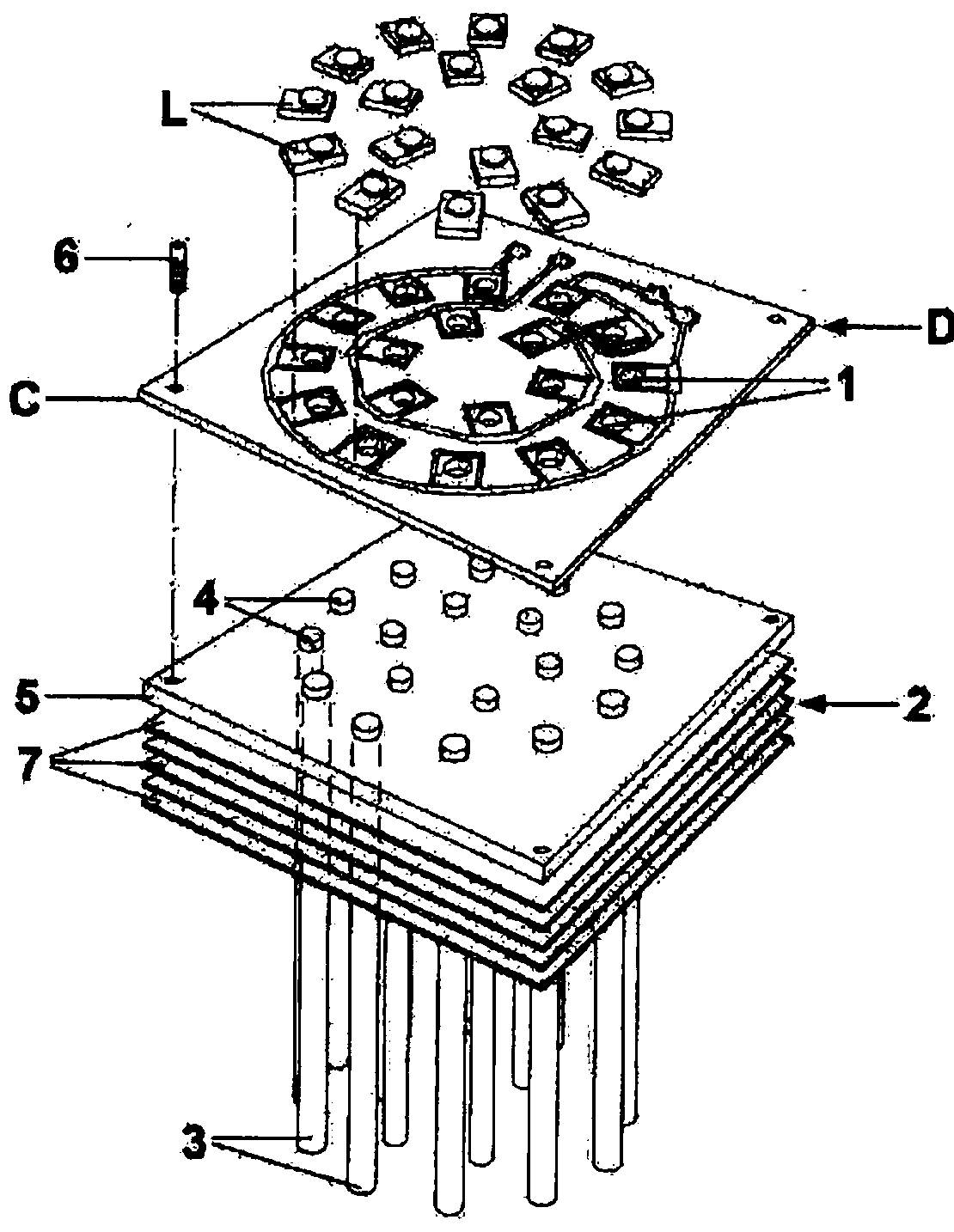
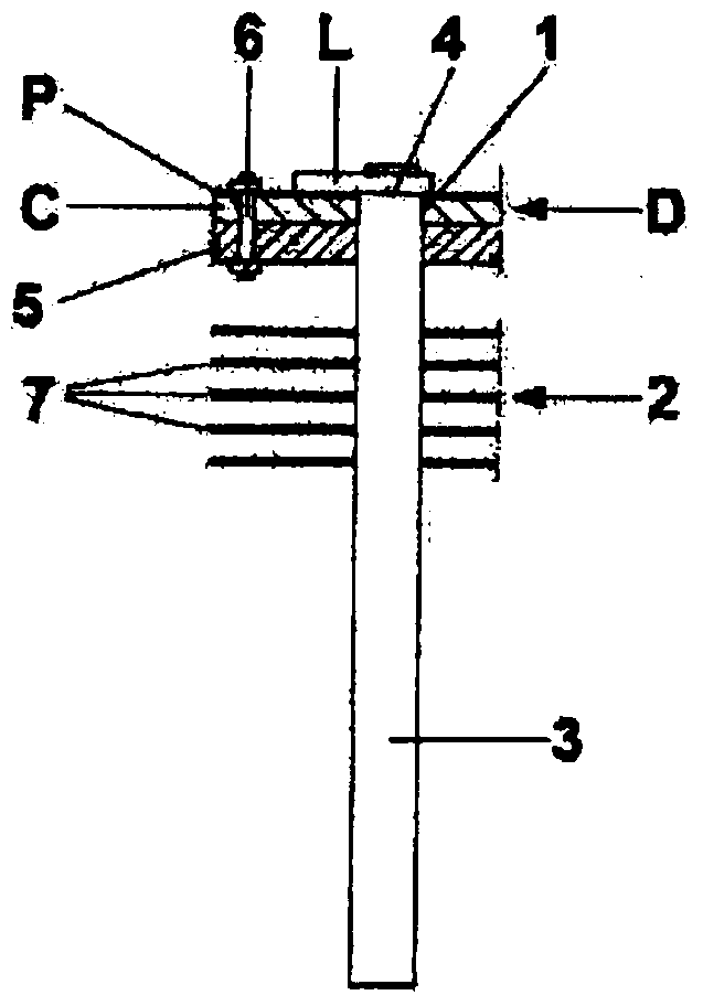
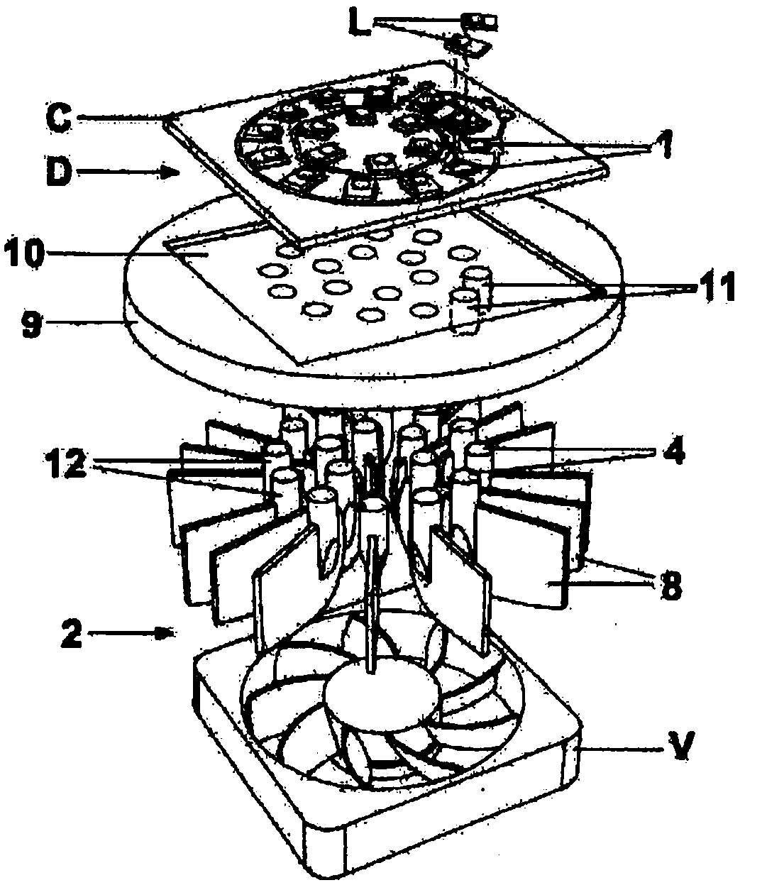
[0035] according to figure 1 and figure 2 In detail, the lighting equipment of the present invention mainly includes:

[0036] - A printed circuit C of the PCB (printed circuit board) or MCPCB (metal core printed circuit board) type, having the function of driving and controlling a matrix of LEDs L, forming the source of illumination for this device D, comprising a housing 1, having a circular hole shape or any other lamp shape of regular geometry configured to accommodate the cooling fins of a specific heat sink 2;

[0037] - a heat sink 2 may be associated with said printed circuit C, comprising a plurality of cooling fins 3, symbolically cylindrical in shape, provided with upper terminals 4, which may be inserted into a corresponding housing 1 of said printed circuit C, attaching the LED forming the source of illumination of the device D directly onto said printed circuit C;

[0038] - a connecting plate 5, included in the structure of said heat sink 2, which is configu...


PUM


Abstract

The present invention concerns a LED (L) lighting device (D) with integrated heatising (2), comprising: a printed circuit (C) of the PCB ( Printed Circuit Board) or MCPCB (Metal Core Printed Circuit Board) type, arranged for electrically and mechanically supporting a LED (L) matrix, forming the light source of said device (D); a heatsink (2) that may be associated in construction to said printed circuit (C), comprising a plurality of cooling fins (3, 8, 13, 14), characterized in that said cooling fins (3, 8, 13, 14) are arranged for being placed into direct contact with said LEDs (L) and each single cooling fin (3, 8, 13, 14) is arranged for dissipating only the heat produced by the specific LEDs (L) applied thereon.; Heatsink (2) comprises cooling fins (3) with a cylindrical shape, (8) with lamellar structure or with prismatic shape with square bases (13) or rectangular bases (14) or with other regular shape, provided with ends (4) arranged for allowing the application of LEDs (L) and made out of high thermally conductive metals or out of composite alloys.

Description

technical field [0001] The present invention relates to lighting technology. [0002] More specifically, the present invention relates to LED lighting devices comprising a heat sink structurally associated with said device. Background technique [0003] It is well known that a negative characteristic of high-power LED lighting is the high temperature generated by the individual LEDs forming the lighting source, compared to optimal optical and color performance and extremely low power consumption. [0004] It is also known that in order to avoid overheating and subsequent irreversible damage to the LEDs, it is essential to supplement the above-mentioned luminaires with suitable heat sinks to ensure proper cooling of the components. [0005] A heat sink adapted to perform the described function, the work of which is based on absorbing the heat generated by the LEDs by conduction and on the basis of further transferring said heat to a plurality of heat sinks of different shape...

Claims


Application Information

Patent Timeline
Patent Type & Authority Applications(China)
IPC IPC(8): F21V29/00
CPCF21Y2101/02F21V29/24F21V29/22F21V29/004F21V29/2231F21V29/262F21V29/2206F21Y2105/001F21V29/2275F21V29/027F21V29/2256F21V29/677F21V29/70F21V29/713F21V29/74F21V29/767F21V29/773F21V29/80F21V29/85F21Y2105/10F21Y2115/10
Inventor 文森佐·达拉斯科
Owner 文森佐达拉斯科
Why Eureka
Try Eureka