Automatic drilling, riveting, forming and positioning device for skin components of aircrafts

An aircraft skin, automatic drilling and riveting technology, applied in positioning devices, metal processing machinery parts, clamping, etc., can solve the problems affecting the mass production efficiency of products and long auxiliary time, so as to improve the quality of assembly riveting and production efficiency, High versatility and reduced preparation time

Inactive Publication Date: 2014-06-25
CHENGDU AIRCRAFT INDUSTRY GROUP
View PDF7 Cites 20 Cited by
  • Summary
  • Abstract
  • Description
  • Claims
  • Application Information

AI Technical Summary

Problems solved by technology

[0003] In order to solve the existing technology of automatic drilling, riveting, forming and positioning of aircraft skin parts in the prior art, it is necessary to prepare multiple sets of fixtures, the auxiliary time for assembling skin parts is long, and the mass production efficiency of products is affected. The invention proposes an aircraft Automatic drilling and riveting forming positioning device for skin parts

Method used


Image

  • Automatic drilling, riveting, forming and positioning device for skin components of aircrafts
  • Automatic drilling, riveting, forming and positioning device for skin components of aircrafts
  • Automatic drilling, riveting, forming and positioning device for skin components of aircrafts

Examples


Embodiment Construction

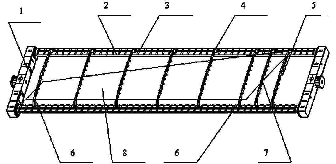
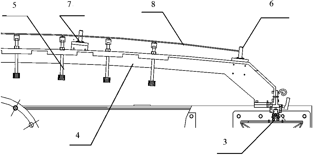
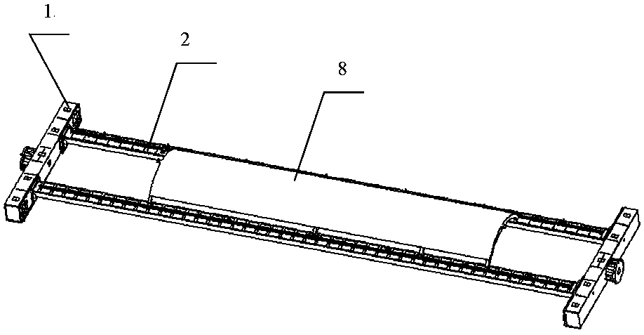
[0011] attached figure 1 It is a three-dimensional schematic diagram of the automatic drilling and riveting forming positioning device for aircraft skin parts of the present invention, with figure 2 It is a front view schematic diagram of the automatic drilling and riveting forming positioning device for aircraft skin parts of the present invention, with the attached image 3 It is a three-dimensional schematic diagram of an embodiment of the automatic drilling and riveting molding positioning device for aircraft skin parts of the present invention. In the figure, 1 is an end beam, 2 is a longitudinal beam, 3 is a linear guide rail, 4 is an arc support plate, 5 is a support screw rod, and 6 is a The positioning pin in X direction, 7 is the positioning pin in Y direction, and 8 is the aircraft skin part. As can be seen from the figure, the automatic drilling and riveting forming positioning device for aircraft skin parts of the present invention adopts the working support fra...


PUM


Abstract

The invention provides an automatic drilling, riveting, forming and positioning device for skin components of aircrafts. The automatic drilling, riveting, forming and positioning device aims to solve problems of large quantities of required tool fixtures, influence on batch production efficiency of products and the like of an automatic drilling, riveting, forming and positioning technology for skin components of aircrafts in the prior art. The skin components of the aircrafts can be formed, positioned and fixed by the aid of a working support frame of a numerical-control bracket system of the automatic drilling, riveting, forming and positioning device. The working support frame comprises two end beams, two longitudinal beams, arc-shaped support plates and support screws; the end beams and the longitudinal beams form a square working support frame, and the longitudinal beams can translate on the end beams and can be fixed onto the end beams; linear guide rails are arranged on horizontal planes of the longitudinal beams; the arc-shaped support plates are radially provided with the support screws, and universal roll balls are arranged at the ends of the support screws. The automatic drilling, riveting, forming and positioning device has the technical advantages that the automatic drilling, riveting, forming and positioning device is adaptive to the skin components of the aircrafts, the skin components with different curved surfaces and different structure sizes can be formed and positioned on the numerical-control bracket system, accordingly, the automatic drilling, riveting, forming and positioning device is high in universality, and the assembling and riveting quality and the production efficiency of the skin components of the aircrafts can be effectively improved.

Description

technical field [0001] The invention relates to an automatic drilling, riveting, forming and positioning technology for aircraft skin parts, in particular to an automatic drilling, riveting and forming positioning device for aircraft skin parts. Background technique [0002] The automatic drilling and riveting assembly system of aircraft skin parts includes two parts: automatic drilling and riveting machine and CNC bracket system. The CNC bracket system is used for positioning and clamping of assembled parts; Fastener installation, etc. Since aircraft skin parts are thin-walled parts, they are characterized by poor rigidity and cannot be molded by themselves. The shape and structure are completely guaranteed by the tooling fixture, which is the product frame. Since the curvature, size and size of aircraft skin parts are not exactly the same, and the supporting arc curvature, structure and size of the product frame are also different, each type of aircraft skin part assembly...

Claims


Application Information

Patent Timeline
Patent Type & Authority Applications(China)
IPC IPC(8): B23Q3/00
CPCB23Q3/062B23P23/00
Inventor 熊红黄中平
Owner CHENGDU AIRCRAFT INDUSTRY GROUP
Why Eureka
Try Eureka