Method for machining optical fiber stress rod

A technology of optical fiber stress and processing method, which is applied in the direction of metal processing equipment, manufacturing tools, grinding/polishing equipment, etc., can solve the problems that affect the grinding accuracy and the jumping of optical fiber stress rod 2, and achieve the improvement of processing accuracy, smoothness, and The effect of enhancing the polishing effect

Active Publication Date: 2014-06-25
武汉长盈通光电技术股份有限公司
View PDF5 Cites 2 Cited by
  • Summary
  • Abstract
  • Description
  • Claims
  • Application Information

AI Technical Summary

Problems solved by technology

The relative position of the optical fiber stress rod and the grinding wheel in the existing grinding process is as shown in the accompanying drawing part of the specification figure 1 As shown in the figure, the grinding wheel 1 and the optical fiber stress rod 2 are set parallel to each other for rolling grinding. Since the grinding wheel 1 and the optical fiber stress rod 2 will interfere with each other, it is easy to cause the beating of the optical fiber stress rod 2, thereby affecting the grinding accuracy.

Method used


Image

  • Method for machining optical fiber stress rod
  • Method for machining optical fiber stress rod

Examples


Embodiment Construction

[0017] Specific embodiments of the present invention will be described in further detail below in conjunction with the accompanying drawings.

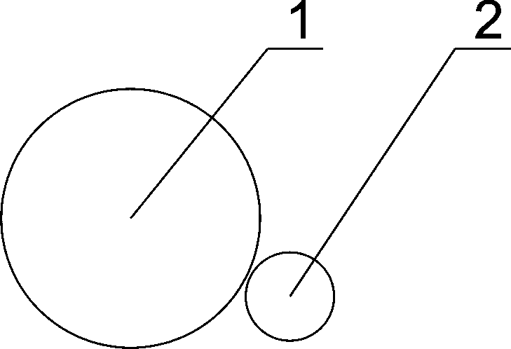
[0018] figure 1 The relative positions of the grinding wheel 1 and the optical fiber stress rod 2 in the existing grinding process of the optical fiber stress rod are illustrated, and since they have been described in detail in the background technology section, they will not be repeated here.

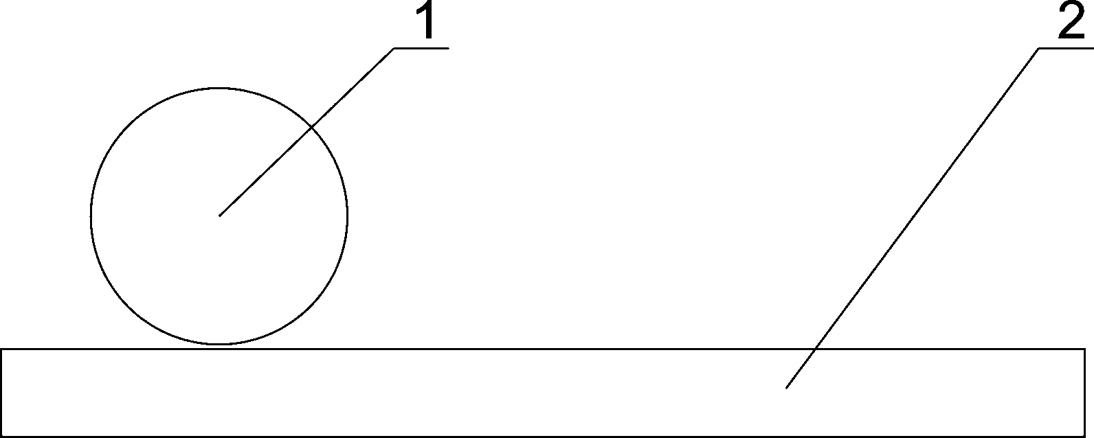
[0019] Such as figure 2 As shown, a processing method of an optical fiber stress rod of the present invention, first prepares an optical fiber stress rod 2 by a conventional method, and then grinds the optical fiber stress rod 2 . In the operation of grinding the optical fiber stress rod 2, the grinding wheel 1 of the grinding equipment and the optical fiber stress rod 2 are vertically arranged, and while the grinding wheel 1 and the optical fiber stress rod 2 rotate around their respective axes, the two along the direction of the optical fib...


PUM

PropertyMeasurementUnit
diameteraaaaaaaaaa

Abstract

The invention discloses a method for machining an optical fiber stress rod. The method includes the steps of making the optical fiber stress rod with a conventional method, and grinding the optical fiber stress rod. The method is characterized in that in the step of grinding the optical fiber stress rod, a grinding wheel of a grinding device is arranged to be perpendicular to the optical fiber stress rod, and the grinding wheel and the optical fiber stress rod oppositely move in the axial direction of the optical fiber stress rod while the grinding wheel and the optical fiber stress rod rotate respectively around shafts. Compared with the prior art, the method has the advantages that the grinding wheel of the grinding device is perpendicular to the optical fiber stress rod, in the grinding process, the direction of the friction force borne by the optical fiber stress rod is changed from the radial direction in the existing mode to the axial direction, radial jumping generated in the grinding process of the optical fiber stress rod is accordingly avoided, the machining accuracy is improved, and the smooth degree of the surface of the grinded optical fiber stress rod is remarkably improved compared with the existing mode; existing line contact between the grinding wheel and the optical fiber stress rod is changed into surface contact, and therefore the polishing effect is improved.

Description

technical field [0001] The invention relates to the preparation of optical fibers, in particular to a method for processing optical fiber stress rods in the optical fiber preparation process. Background technique [0002] Optical fiber stress rods are one of the important materials used to manufacture optical fibers. Taking the manufacturing process of Panda-type polarization-maintaining optical fiber as an example, it first uses PCVD to manufacture optical fiber preforms and high-concentration boron-doped stress rods respectively; then uses quartz deep hole technology to punch two pre-designed symmetrical circular holes in the optical fiber preforms , and then insert the boron-doped stress rod into the perforated optical fiber preform to form a panda-shaped polarization-maintaining optical fiber preform; finally, the panda-shaped polarization-maintaining optical fiber preform is drawn through a drawing tower to obtain a panda-shaped polarization-maintaining optical fiber. ...

Claims


Application Information

Patent Timeline
Patent Type & Authority Applications(China)
IPC IPC(8): B24B5/04
CPCB24B5/045
Inventor 谢利华袁曚皮亚斌
Owner 武汉长盈通光电技术股份有限公司
Why Eureka
Try Eureka