Dual-purpose three-claw puller

A three-jaw puller and dual-purpose technology, which is applied in the direction of hand-held tools and manufacturing tools, can solve the problems of inaccurate fixing, helplessness in removing the circlip, and adjustment of the length of the lever handle, etc., so as to improve the effect of force application and have a wide range of applications , the effect of increasing the force surface

Inactive Publication Date: 2014-06-25
UNIV OF SHANGHAI FOR SCI & TECH
View PDF5 Cites 11 Cited by
  • Summary
  • Abstract
  • Description
  • Claims
  • Application Information

AI Technical Summary

Problems solved by technology

However, the length of the lever handle is fixed, and the general size is very long. It cannot effectively adjust the length of the lever handle according to the tightness of the parts to be disassembled, resulting in waste of materials. At the same time, pressurize once, and the stroke of the pressurizing rod is very short and cannot be adjusted.
[0005] Whether it is a mechanical puller or a hydraulic puller that exists on the market at present, see the pullers described in Chinese patents CN 2584342Y, CN 203185270 U, etc., there are basically the following three problems: 1. The opening and closing angles of some pullers are adjustable , but cannot be precisely fixed
2. With the adjustment of the opening and closing angle of the puller, it cannot guarantee surface contact between the hook seat and the fastener. In fact, it is line contact or point contact in most cases, and it is easy to damage the hook seat and the fastener. Contact surfaces
3. Due to the singleness of the ejector rod, the puller is currently only suitable for dismantling the fastening parts on the shaft such as couplings, gears, bearings, pulleys, etc., but it is helpless to disassemble the clutch assembly and some circlips

Method used


Image

  • Dual-purpose three-claw puller
  • Dual-purpose three-claw puller
  • Dual-purpose three-claw puller

Examples


specific Embodiment approach

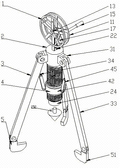
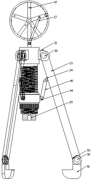
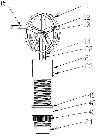
[0031] The specific implementation method: when adopting three-legged thimble 251 ( Image 6 ), adjust the opening and closing angle of the tripod on the three-legged thimble 251 according to clutches of different sizes, so that the three pressure rods can fit the pressure plate of the clutch, and then shake the rocking handle 15 to drive the pressure rod 22 to move. To achieve the purpose of dismantling the clutch; when the conical thimble 252 is used, the conical thimble 252 is directly pressed against the shaft end of the part, and then the rocker 15 is shaken, and the rocker 17 will drive the pressure rod 22 to pressurize the hydraulic cylinder and push The conical thimble 252 moves so that the parts can be slowly removed. If you want to adjust the speed and stroke of the push rod 22, the rocking rod 17 can be fixed on the positioning holes 12 at different positions by the pin shaft 16.

[0032] The claw device 3 is made up of a large hinged joint 31, a pin shaft 32, a cl...


PUM


Abstract

The invention relates to a dual-purpose three-claw puller. The upper surface of a cylinder body of a hydraulic oil cylinder device is fixedly connected with a rotary pressurization device through a supporting frame, the lateral surface of the upper portion of the cylinder body is movably connected with a pulling claw device, the lower portion of the cylinder body is in threaded connection with a bearing assembly, and a claw hook rod of the pulling claw device is provided with a claw hook device. According to the dual-purpose three-claw puller, a rocking rod can be hinged to different positioning holes according to the tightness of a fastener, and therefore the stroke and speed of a pressurization rod when a wheel hub rotates by one circle are changed, and the force application effect is improved. The opening and closing angle of a puller hook claw can be accurately adjusted and fixed through the bearing assembly and will not change along with the change of the angle of a work space, and then the fastener can be detached vertically or horizontally. A claw hook seat and the fastener keep surface contact all the time through a limiting spring, the stress surface is increased, damage to the contact surfaces of the claw hook seat and the fastener caused by linear contact or point contact is avoided, the fastener on a shaft and a clutch assembly can be detached by replacing different ejection pins, and the dual-purpose three-claw puller is wide in application range.

Description

technical field [0001] The invention relates to a mechanical dismantling device, in particular to a dual-purpose three-jaw puller with integrated manual hydraulic pressure and adjustable opening and closing angles. Background technique [0002] At present, pullers are widely used to disassemble fastening parts on shafts such as various couplings, gears, bearings, and pulleys. Basically can be divided into two categories: mechanical puller and hydraulic puller. [0003] The mechanical puller works by screwing in and out of the thread between the hook seat and the push rod. When manually screwing in and out of the screw thread, it is laborious and cumbersome, and when the screwing length is long, it is extremely inconvenient. [0004] The hydraulic puller is pressurized by swinging the pressurized handle to drive the hydraulic ejector rod, so that the ejector rod advances steadily forward, and the hook claws retreat accordingly to pull out the pulled object. However, the le...

Claims


Application Information

Patent Timeline
Patent Type & Authority Applications(China)
IPC IPC(8): B25B27/02
CPCB25B27/026
Inventor 王猛李凯李俊生孙猛高建伟王莹莹
Owner UNIV OF SHANGHAI FOR SCI & TECH
Why Eureka
Try Eureka