A block cutting feeding conveying mechanism

The technology of feeding mechanism and conveying mechanism is applied in the field of block cutting feeding and conveying mechanism, which can solve the problems of low automation degree, unstable cutting and low production efficiency of the production line, and achieve good stability, improve adaptability and reduce noise. Effect

Active Publication Date: 2016-02-24
广州瑞雪农业有限公司
View PDF8 Cites 0 Cited by
  • Summary
  • Abstract
  • Description
  • Claims
  • Application Information

AI Technical Summary

Problems solved by technology

[0003] In order to solve the problems of unsteady cutting, low degree of automation of the production line and low production efficiency during the cutting process of the blocks of the current block cutting machine tools, the present invention proposes a machine that can not only ensure thorough cutting, but also facilitate the removal of cooling water. And it can ensure that the material will not be taken up by the saw blade to achieve continuous and stable thorough cutting, and the block cutting feeding and conveying mechanism can be sent away quickly after cutting

Method used


Image

  • A block cutting feeding conveying mechanism
  • A block cutting feeding conveying mechanism
  • A block cutting feeding conveying mechanism

Examples


Embodiment 1

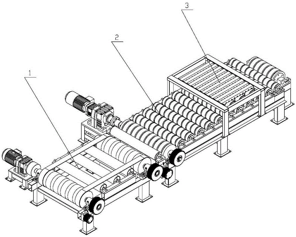
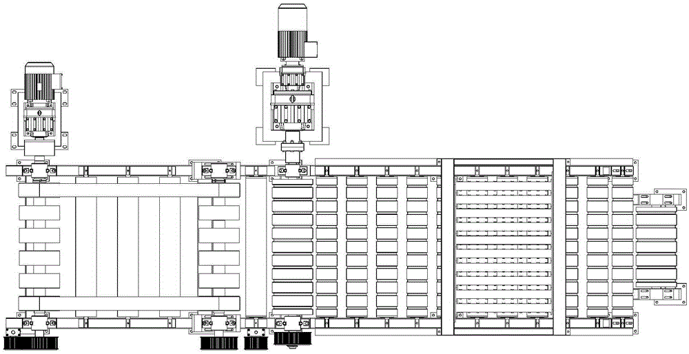
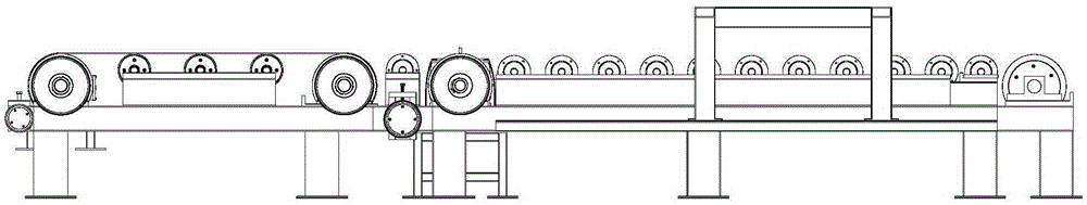
[0030] Embodiment 1 A block cutting feeding conveyor according to the present invention includes a conveying mechanism 1, a feeding mechanism 2 and a pressing mechanism 3, and the end of the conveying mechanism 1 is fixed to the front end of the feeding mechanism 2; The pressing mechanism 3 is installed above the feeding mechanism 2; the conveying mechanism 1 includes a conveying mechanism frame 11, a conveying motor fixing frame 12, a reduction motor 13, a first roller 14, a first synchronous belt Wheel 15, the deceleration motor 13 is installed on the conveying motor fixed frame 12; the first roller 111 and the second roller 112 parallel to each other are respectively installed on the bearings at the two ends of the conveying mechanism frame 11, the first The same end of the roller 111 and the second roller 112 is equipped with a first synchronous pulley 113 respectively, wherein the other end of the first roller 111 is connected with the output shaft of the reduction motor 1...

Embodiment 2

[0042] Embodiment 2 Combined with the figure, the present invention includes a set of feeding mechanism, which is powered by a motor and connected with the driving roller through a coupling, and the driving roller is cut with a V-belt groove, so that the V-belt can be installed and can ensure that the V-belt is in motion. The V-belt bypasses the first tensioning roller and the second tensioning roller respectively, while the first tensioning roller is fixed on the slide plate and is slidably connected with the fixed plate. When the bolt is rotated, the slide plate is driven to drive the second The tensioning roller moves to play the role of tensioning; the second tensioning roller is fixed on the supporting seat, and the supporting seat is slidingly connected with the fixed plate. When the bolt is rotated, the supporting seat is pulled and the second tensioning roller is driven to move. So as to play the role of tension; the first tension roller is installed on the frame of the...


PUM


Abstract

The invention discloses a building block cutting, feeding and conveying mechanism which comprises a conveying mechanism, a feeding mechanism and a first compressing mechanism. The tail end of the conveying mechanism is fixed to the front end of the feeding mechanism; the first compressing mechanism is mounted above the feeding mechanism; the conveying mechanism comprises a conveying mechanism frame, a conveying motor fixing frame, a gear motor, a first roller and a first synchronous belt pulley, the feeding mechanism comprises a motor fixing frame, a motor, a transitional roller, a driving roller, a second compressing mechanism, a feeding mechanism frame, a first tension roller and a second tension roller, the second tension roller is arranged at the tail end of the feeding mechanism frame, the first compressing mechanism comprises compressing wheel fixing plates, compressing wheel frames and compressing wheels, and the bottoms of the compressing wheel frames are mounted on supporting steel angles of the feeding mechanism frame; the compressing wheels are connected onto the compressing wheel fixing plates by shafts, and rolling surfaces of the compressing wheels are positioned above first supporting rollers. The building block cutting, feeding and conveying mechanism has the advantages that by the aid of the building block cutting, feeding and conveying mechanism, building blocks can be continuously and stably cut, can be assuredly thoroughly cut and can be quickly conveyed after being cut, accordingly, the efficiency can be improved, and the labor intensity of staffs can be relieved.

Description

technical field [0001] The invention relates to a block cutting feeding conveying mechanism. Background technique [0002] With the rapid development of modern industry, the limitations of block cutting machine tools and cutting technology currently used by enterprises lead to the discontinuity of the entire cutting process, low degree of automation of the production line, low production efficiency, large labor energy consumption, poor working environment, and blocks in During the cutting process, the cutting is not stable, discontinuous, and not thorough. The existing cutting machines either cannot cut through, or the material floats on the water, which is prone to drift; second, during the cutting process, the cut through material is easy to be caught Flying between the saw blades, the cutting speed cannot be increased during production, these factors have greatly increased the scrap rate, increased production costs and caused a great waste of social resources. Therefore ...

Claims


Application Information

Patent Timeline
Patent Type & Authority Patents(China)
IPC IPC(8): B28B11/14B65G13/02B65G13/07
CPCB28B11/14B65G13/02B65G13/07
Inventor 秦宝荣蔡欢刘江余敏文
Owner 广州瑞雪农业有限公司
Why Eureka
Try Eureka