Multifunctional polar coordinate instrument

A polar coordinate and multifunctional technology, applied in the field of multifunctional polar coordinate instruments, can solve the problems of troublesome operation, difficult to measure the polar diameter, inconvenient operation, etc., and achieve the effects of low manufacturing cost, convenient use and portability.

Inactive Publication Date: 2016-02-03
张松吉 +2
View PDF8 Cites 0 Cited by
  • Summary
  • Abstract
  • Description
  • Claims
  • Application Information

AI Technical Summary

Problems solved by technology

This instrument can also be used to plot polar coordinates, but there are obviously the following problems in using it to plot polar coordinates: when the center of the protractor’s rotating shaft is positioned at the pole of the polar coordinates through the hollow rotating shaft screw, an auxiliary tool, the center needle, is required. It is more troublesome, if the misalignment between the center of the protractor shaft and the pole is not easy to observe during use; when using the vernier on the ruler to slide back and forth to measure the pole diameter, it is easy to cause the corresponding degree misalignment of the ruler and the distance between the center of the protractor shaft and the pole Misalignment; the straightedge is placed on the protractor, and the straightedge is easy to conflict with the operator's hand when it turns around, which is not only inconvenient to operate, but also easily causes misalignment between the center of the protractor shaft and the pole; the straightedge is placed on the protractor. If the ruler hangs above the drawing or the ruler bends and touches the drawing, it is not easy to measure the polar diameter accurately.
In addition, there is a blind area between the diameter of its protractor and its straight edge. In this blind area, due to the occlusion of the protractor, it is impossible to draw polar coordinates in this area.

Method used


Image

  • Multifunctional polar coordinate instrument
  • Multifunctional polar coordinate instrument
  • Multifunctional polar coordinate instrument

Examples


Embodiment Construction

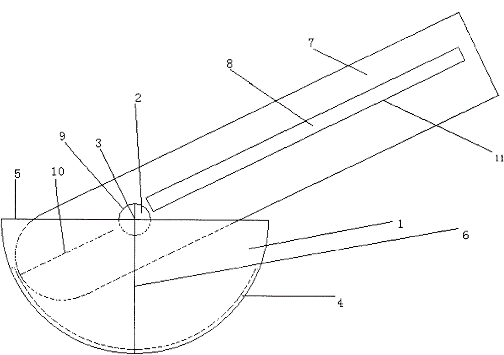
[0021] figure 1 It is a top view of the multifunctional polar coordinate instrument of the present invention. The dial 1 and the ruler 7 are combined together through the shaft 2 on the dial 1 and the round hole 9 on the ruler 7. The ruler 7 is under the dial 1, and the ruler 7 can rotate 180 degrees around the shaft 2.

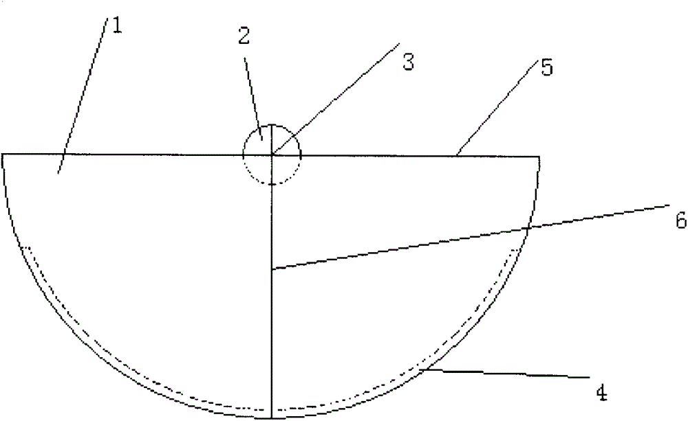
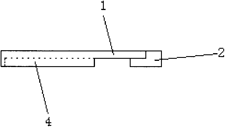
[0022] figure 2 It is a top view of the middle plate 1 of the instrument. The dial 1 is semicircular and made of colorless transparent plastic. The edge of the front arc of the dial 1 is engraved with a degree scale from one end of the diameter 5 to the other end, and is marked with two rows of degree values ​​of 0-180 degrees and 180-0 degrees. At the center of the circle on the reverse side of the dial 1, there is a cylindrical shaft 2 perpendicular to the dial 1, the upper surface of the shaft 2 is on the same plane as the front of the dial 1, and the axis of the shaft 2 passes through the center of the dial 1 . The diameter 5 of the dial 1 and the r...


PUM


Abstract

The invention relates to a multifunctional polar coordinate instrument for potting a polar coordinate. The multifunctional polar coordinate instrument is composed of a semicircle colorless and transparent plastic dial and a white nontransparent plastic ruler, the dial and the ruler are combined together through a shaft in the circle center of the back face of the dial and a circular hole in the ruler, and the ruler can perform 180-degree rotation below the dial. A reticule is formed by the diameter of the dial and the radius corresponding to the 90-degree scale on the upper surface of the shaft. A side wall perpendicular to the dial is arranged at the arc-shaped edge of the back face of the dial, the side wall and the shaft are equal in height, and the height is slightly larger than the thickness of the ruler. The zero graduation end of the ruler is in an arc shape, the right middle, close to the arc-shaped end, of the ruler is provided with a cylindrical circular hole, and the diameter of the circular hole is slightly larger than the diameter of the shaft on the dial. An indicating line pointing to the circle center of the upper bottom face on the circular hole is arranged at the arc-shaped end. A cuboid-shaped groove hole is formed form the circular hole to the other end of the ruler, one long edge of the upper bottom face on the groove hole, the indicating line and the circle center of the upper bottom face of the circular hole are in the same straight line, length scales are arranged on the long edge, and a zero point is located on an axis of the circular hole.

Description

technical field [0001] The invention relates to a tool for plotting polar coordinates, in particular to a multifunctional polar coordinate instrument composed of a dial and a ruler. Background technique [0002] The polar coordinate system is a coordinate system in which the position of a point is represented by a distance and an angle in a plane. At present, in work and study, in order to draw the polar coordinates of a certain point on the drawing, you first need to use a protractor, align the center of the protractor with the pole, make the zero-degree line coincide with the polar axis, and the scale value of the protractor is equal to the polar angle Point a point on the position of the polar angle to determine the position of the terminal edge of the polar angle; then use a straightedge to pass through the pole and the point on the terminal edge of the polar angle to make a ray, and then measure a section equal to the polar diameter from the pole on the ray line segmen...

Claims


Application Information

Patent Timeline
Patent Type & Authority Patents(China)
IPC IPC(8): B43L13/00
Inventor 张松吉李则怡吉星张莽原
Owner 张松吉
Why Eureka
Try Eureka