Method and apparatus for bonding workpieces

A workpiece and process technology, applied in the field of workpiece lamination devices, can solve problems such as workpiece position deviation, decline in yield, workpiece positioning, etc., and achieve the effect of achieving yield, curing shrinkage reduction, and positioning accuracy.

Active Publication Date: 2014-06-25
SHIN ETSU ENG
View PDF5 Cites 5 Cited by
  • Summary
  • Abstract
  • Description
  • Claims
  • Application Information

AI Technical Summary

Problems solved by technology

[0009] However, in the aforementioned conventional workpiece bonding method, a part of the adhesive (UV curable resin) is temporarily cured by UV irradiation, and then the entire large area of ​​the adhesive is fully cured by UV irradiation. As in recent years, the structural strength of the workpiece itself has decreased, and the temperature of the entire workpiece has risen due to the energy imparted by UV irradiation for the main curing of the entire large-area adhesive, and the large-area adhesive has curing shrinkage, etc. Deformation such as warping or distortion occurs, and position deviation occurs between temporarily fixed workpieces
[0010] Therefore, there is a problem that the workpieces cannot be positioned with high precision, and the yield rate decreases.
[0011] In particular, when bonding a display panel with a circuit board connected by sandwiching a flexible board (FPC) from one side of the workpiece, the thickness of the adhesive (UV curable resin) at the place where the flexible board is inserted becomes thicker than that of the other The thickness of the adhesive is thick, so even if the multiple parts of the adhesive are temporarily cured by UV irradiation in the form of dots while the overlapping positions of the workpieces are determined, the UV irradiation for the main curing is compared to the entire adhesive. The energy applied to a large area makes the point-like temporary solidification position become a fulcrum and the entire workpiece becomes easily deformed, and the temporarily fixed workpieces are shifted to the other side, etc., and the required positioning accuracy of the workpieces cannot be achieved.

Method used


Image

  • Method and apparatus for bonding workpieces
  • Method and apparatus for bonding workpieces
  • Method and apparatus for bonding workpieces

Examples


Embodiment 1

[0092] Next, various embodiments of the present invention will be described with reference to the drawings.

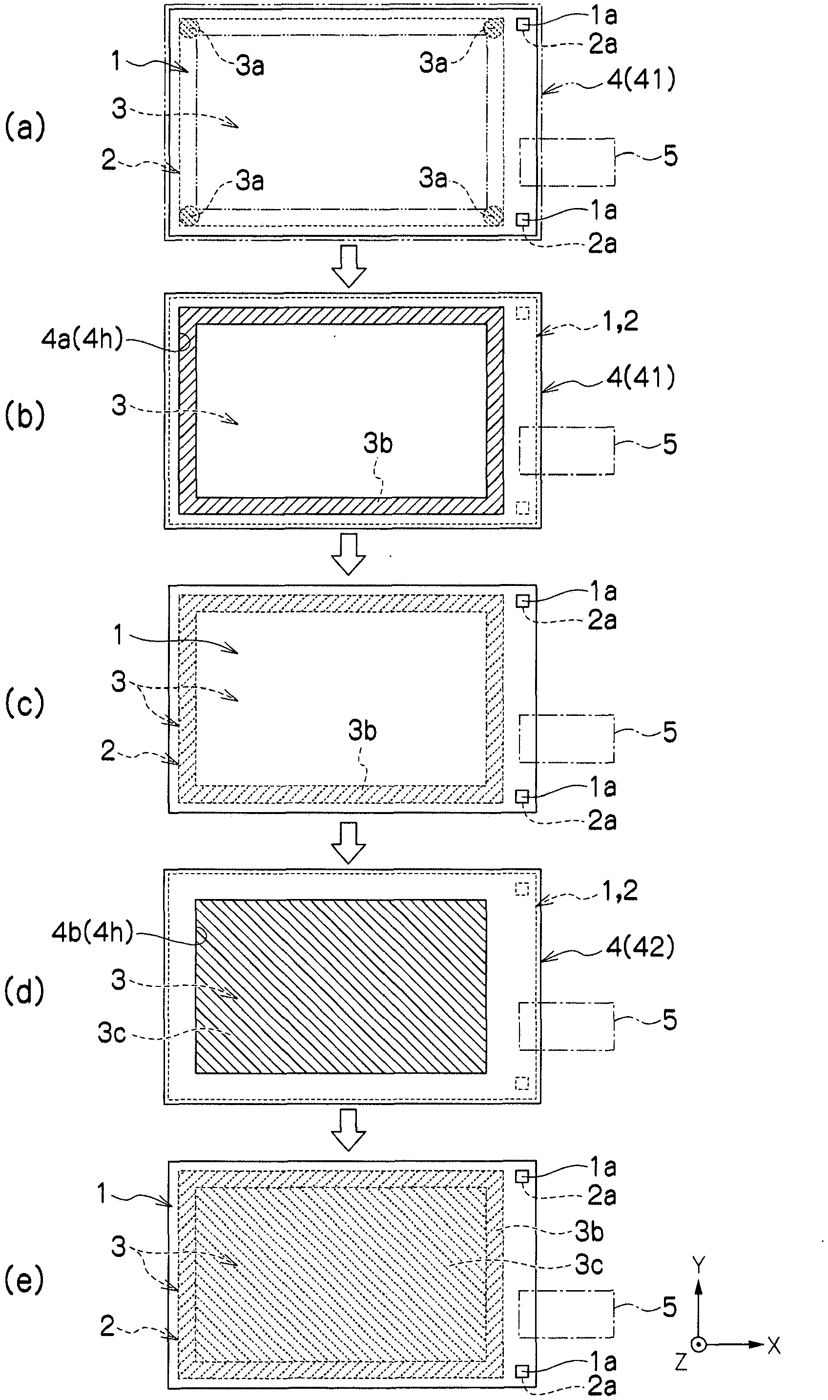
[0093] like figure 1 As shown in (a) to (e), in the workpiece bonding method according to Example 1 of the present invention, the adhesive 3 is sandwiched between the workpieces 1 and 2 in a rectangular shape smaller than the outer shapes of the workpieces 1 and 2 . As a plurality of light-shielding masks 4 with different light-transmitting shapes, in the first step in the main curing process, a first light-shielding mask 41 having a first light-shielding pattern 4a with a frame-shaped light-transmitting hole 4h opened is used. In the next second time, use the second light-shielding mask 42 having the second light-shielding pattern 4b opened with the rectangular light-transmitting hole 4h to divide the divided regions 3b and 3c of the adhesive 3 into two times, sequentially and respectively. Perform partial formal curing.

[0094] That is, with respect to the frame-s...

Embodiment 2

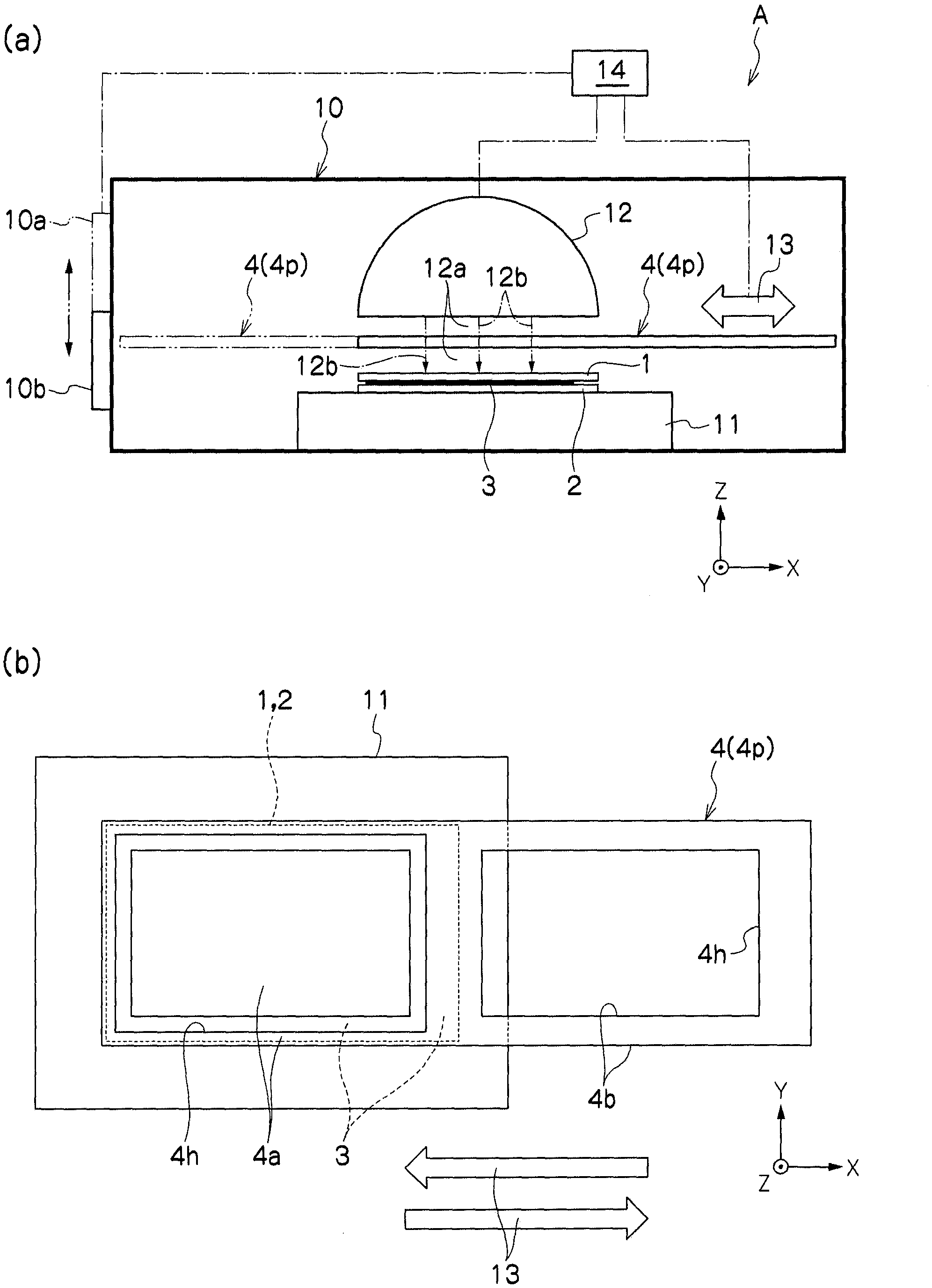
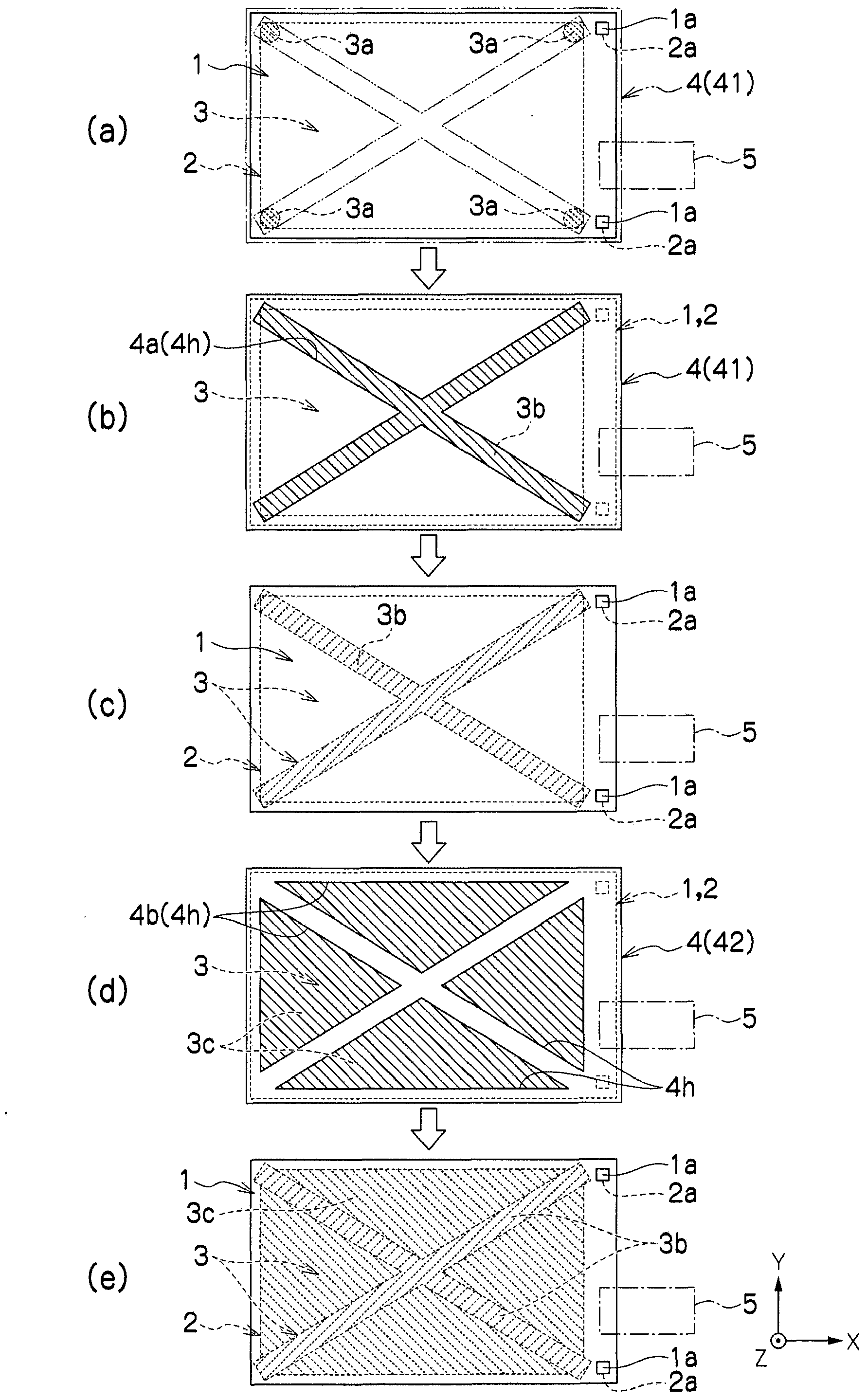
[0104] like image 3 (a)~(e) and Figure 4 As shown in (a) and (b), in the workpiece bonding method according to Example 2 of the present invention, as various kinds of light-shielding masks 4 with different light-transmitting shapes, in the first time of the main curing process, use Have the first light-shielding mask 41 of the first light-shielding pattern 4a that is opened with the X-shaped light-transmitting hole 4h along the diagonal line of the rectangular adhesive 3, in the next second time, use the first light-shielding mask 41 that has the X-shaped light-transmitting hole 4h that is opened with The second light-shielding mask 42 of the second light-shielding pattern 4b of the (4) triangular light-transmitting holes 4h sandwiched by the diagonals of the rectangular adhesive 3 divides the divided regions 3b and 3c of the adhesive 3 twice , sequentially, respectively, for partial formal solidification, this structure is the same as figure 1 and figure 2 The example 1...

Embodiment 3

[0110] like Figure 5 As shown in (a) to (e), in the workpiece bonding method according to Example 3 of the present invention, as a plurality of types of light-shielding masks 4 with different light-transmitting shapes, in the first step of the main curing process, a Have the first light-shielding mask 41 of the first light-shielding pattern 4a that is opened with the frame-shaped light-transmitting hole 4h, in the next second time, use the first light-shielding mask 41 that has the light-shielding pattern 4h that is opened with the square black-and-white checkered shape. The second light-shielding mask 42 of the second light-shielding pattern 4b, in the next third time, use the third light-shielding mask 43 of the third light-shielding pattern 4c having the light-transmitting holes 4h of the square black and white checkered pattern, The divided regions 3b, 3c, and 3d of the adhesive 3 are divided into 3 times, sequentially, and partially formally cured respectively. This stru...


PUM


Abstract

The invention provides a method and an apparatus for bonding workpieces, which suppresses workpiece deformation and adhesive solidification contraction and simultaneously causes the adhesive to solidify integrally and formally. The apparatus for bonding the workpiece according to the invention causes one part of the adhesive (3) clamped between the overlapped workpiece (1,2) to partially and temporarily solidify and the workpieces (1,2). Afterwards, the adhesive (3) is integrally divided into a plurality of areas and partial formal solidification occur on divided areas (3b,3c,3d) in multiple times successively. Therefore, even total area of integer of the adhesive (3) is large, the parts which are divided into a plurality of narrow areas are respectively and successively solidified. Therefore, compared with a method of formally solidifying integer of large-area adhesive in one time, the method provided by the invention is advantageous in that temperature increase amount of the workpieces (1,2) in each time of formal solidification and solidification contraction amount of the divided areas (3b,3c,3d) in the adhesive (3) are greatly reduced.

Description

technical field [0001] The present invention relates to a method for bonding a plate-shaped workpiece such as a FDP such as a flat panel display (FPD) or a touch panel or a 3D (3-dimensional) display or an electronic book to another plate-shaped workpiece such as a protective glass or an FPD with an adhesive. A workpiece bonding method for workpieces and a workpiece bonding device for implementing the method. Background technique [0002] Conventionally, such a workpiece bonding method and workpiece bonding device are known in which an adhesive (UV curable resin) is supplied to one side of at least one workpiece so that the adhesive spreads over the entire surface, and then the bonding agent is applied Bond another workpiece on the adhesive, and then irradiate the outer edge of the adhesive that spreads over at least one surface of the bonded pair of workpieces with electromagnetic waves (UV light) for temporary curing, thereby only The outer edge of the adhesive forms a te...

Claims


Application Information

Patent Timeline
Patent Type & Authority Applications(China)
IPC IPC(8): C09J5/00
CPCG02F1/1303G02F1/133308B32B37/0046B32B37/12G09F9/00B32B2037/1253B32B2307/412B32B2457/20G02F1/133331H10K50/841H10K71/00
Inventor 横田道也
Owner SHIN ETSU ENG
Why Eureka
Try Eureka