Special probe passing through inside of perineum pelvic floor ultrasonic cavity

A pelvic floor and ultrasound technology, applied in the directions of ultrasonic/sonic/infrasonic diagnosis, application, and sonic diagnosis, can solve problems such as insufficiency, insufficient technology, insufficient experience, etc., to achieve good use effect, strong adaptability and practicality strong effect

Pending Publication Date: 2018-11-06
PEKING UNIV SHENZHEN HOSPITAL
View PDF4 Cites 2 Cited by
  • Summary
  • Abstract
  • Description
  • Claims
  • Application Information

AI Technical Summary

Problems solved by technology

[0005] In the above three inspection steps, it is difficult for medical staff who are not experienced enough and not comprehensive enough to control the depth of insertion into the patient's vagina when holding the required intracavitary ultrasound probe, especially in the first In the first step and the second step, during the first step, it is easy to make the end of the intracavitary ultrasound probe to enter the patient's vagina; The depth of the end of the internal ultrasound probe into the patient's vagina is much more than 2.0cm or far less than 2.0cm, which makes it impossible to meet the required inspection

Method used


Image

  • Special probe passing through inside of perineum pelvic floor ultrasonic cavity
  • Special probe passing through inside of perineum pelvic floor ultrasonic cavity
  • Special probe passing through inside of perineum pelvic floor ultrasonic cavity

Examples


Embodiment Construction

[0039] The technical solution of the present invention will be described in detail below in conjunction with the accompanying drawings and specific embodiments, so as to understand the essence of the present invention more clearly and intuitively.

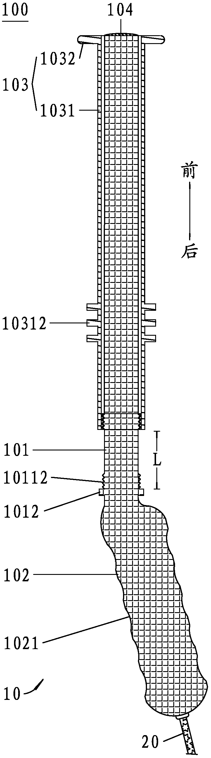
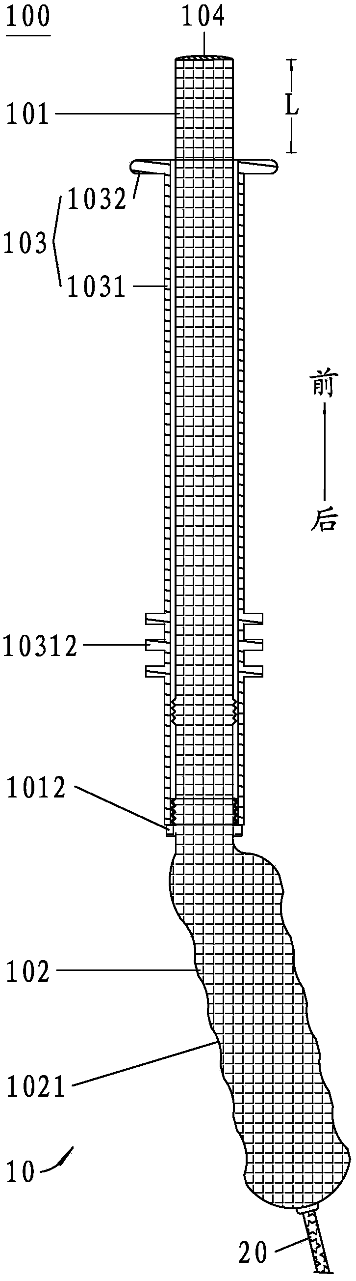
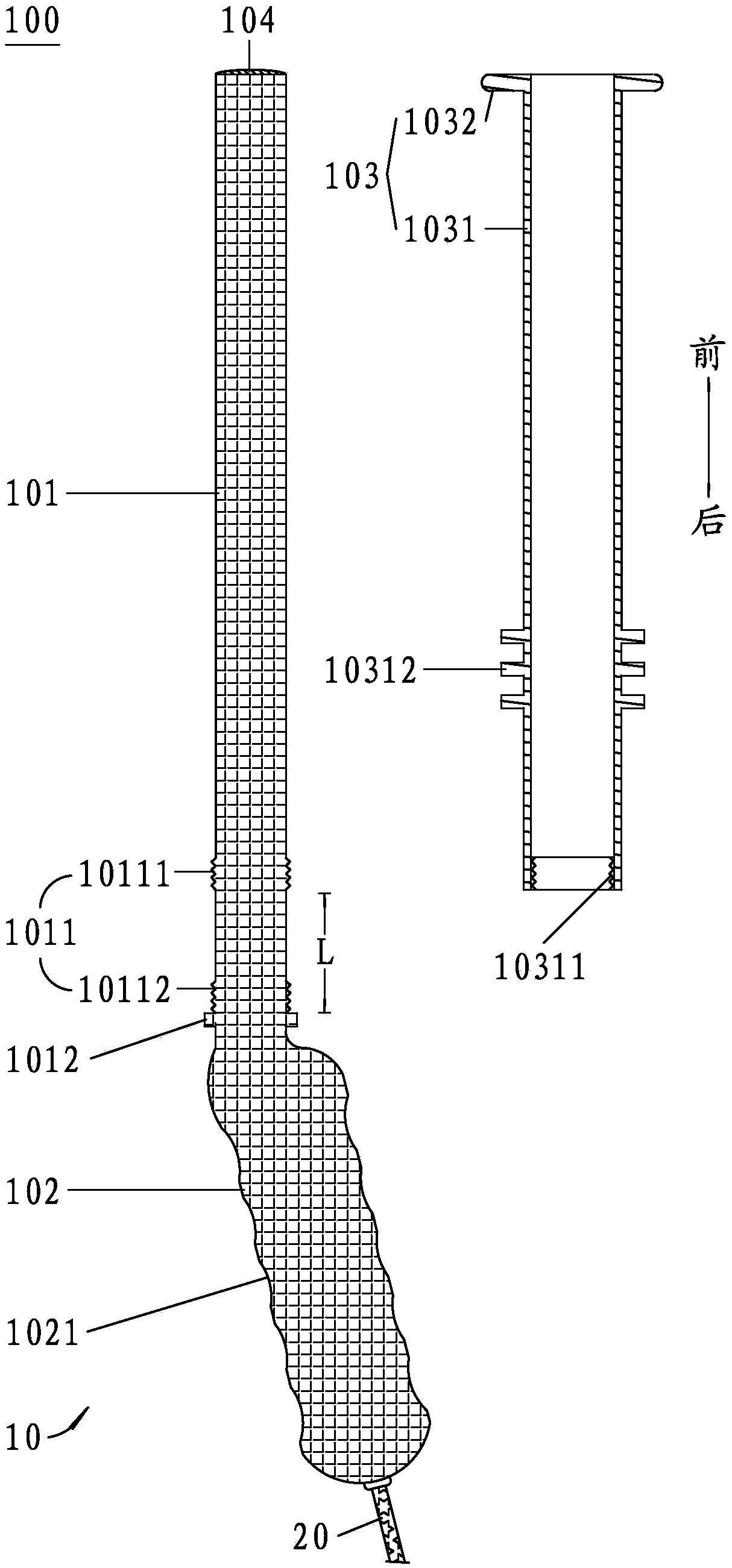
[0040] combine figure 1 , figure 2 and image 3 shown;

[0041] A special probe 100 for transperineal pelvic floor ultrasonic cavity provided by the present invention includes a housing 10, an ultrasonic transducer arranged in the front end of the housing 10, and a self-contained sensor connected to the ultrasonic transducer. The signal connection line 20 drawn from the tail end of the housing 10 is improved in the present invention in that: the housing 10 includes a cylindrical protruding part 101 at the front end suitable for insertion into the patient's vagina, a circular ring at the rear end suitable for holding The cylindrical handle 102 and the stopper arranged outside the cylindrical protruding part 101 and adapted to abut...


PUM


Abstract

The invention discloses a special probe passing through the inside of a perineum pelvic floor ultrasonic cavity, which comprises a shell, an ultrasonic transducer arranged in the front end of the shell and a signal connection line which is connected with the ultrasonic transducer and lead from the tail end of the shell. The shell comprises a cylindrical extending-in part, a cylindrical hand-held part and a blocking part, wherein the cylindrical extending-in part is positioned at the front end and is suitable to insert into the vagina of a patient; the cylindrical hand-held part is positioned at the rear end and is suitable to hold with a hand; the blocking part can move front and back, is arranged outside the cylindrical extending-in part, is suitable to press against and adhere to the peripheral edge of the vaginal orifice of the patient and is used for defining the insertion depth of the end head of the cylindrical extending-in part in the vagina of the patient. The special probe passing through the inside of the perineum pelvic floor ultrasonic cavity has the beneficial effects that when the front-and-back position of the blocking part outside the cylindrical extending-in part is regulated, the insertion depth of the end head of the cylindrical extending-in part in the vagina of the patient is adjustable, and thus, the special probe can conveniently regulate the blocking part to a required position to define the insertion depth of the end head of the cylindrical extending-in part in the vagina of the patient, so that the special probe can conveniently carry out step-by-step checking on the patient in the perineum pelvic floor ultrasonic cavity, and is convenient and reliable to use, high in practicality and good in use effect.

Description

technical field [0001] The invention relates to the technical field of medical equipment, in particular to a special probe for transperineal pelvic floor ultrasonic intracavity. Background technique [0002] An ultrasonic probe, also known as an ultrasonic probe, is a device that emits and receives ultrasonic waves during ultrasonic testing. The performance of the probe directly affects the characteristics of the ultrasonic wave and affects the detection performance of the ultrasonic wave. [0003] The probe used in ultrasonic testing is a transducer that uses the piezoelectric effect of materials to convert electrical energy and acoustic energy. The key component in the probe is the wafer, which is a single crystal or polycrystalline sheet with piezoelectric effect, and its function is to convert electric energy and acoustic energy into each other. [0004] In major hospitals, for patients undergoing perineal pelvic floor ultrasound examination, when using common intracav...

Claims


Application Information

Patent Timeline
Patent Type & Authority Applications(China)
IPC IPC(8): A61B8/12
CPCA61B8/12A61B8/4444A61B8/445
Inventor 王玥贺沁洋
Owner PEKING UNIV SHENZHEN HOSPITAL
Why Eureka
Try Eureka