Rammer release device of dynamic compactor

A technology of dynamic tamping machine and hammer removal, which is applied in soil protection, construction, infrastructure engineering, etc., can solve the problems of high cost, complicated operation, and high free height of the hammer removal device, so as to improve work efficiency and reduce free height , the effect of improving stability

Inactive Publication Date: 2014-06-25
ANHUI LIUGONG CRANE
View PDF6 Cites 7 Cited by
  • Summary
  • Abstract
  • Description
  • Claims
  • Application Information

AI Technical Summary

Problems solved by technology

[0003] At present, there are four defects in the hammer release device commonly used in dynamic tamping machines: 1. The hammer release wire rope is easy to touch the tamper, which reduces the stability of the hammer release; 2. The traditional load-bearing hook and the release hook are combined through a flexible hammer release wire rope The hammer removal device is formed. The combined hammer removal device has a high free height, which not only reduces the lifting height of the rammer and the rated tamping per...

Method used


Image

  • Rammer release device of dynamic compactor
  • Rammer release device of dynamic compactor
  • Rammer release device of dynamic compactor

Examples


Embodiment Construction

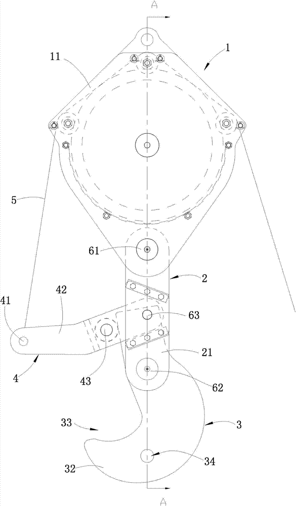
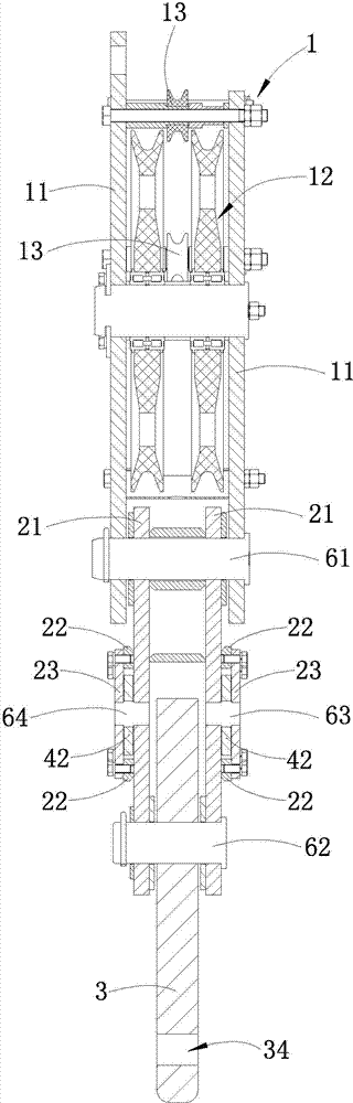
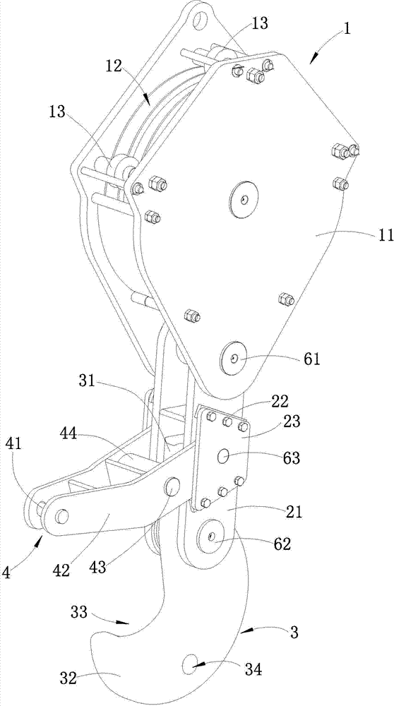
[0022] Such as Figures 1 to 3 shown (for ease of understanding, figure 2 and image 3 Omit the hammer wire rope 5)

[0023] The hammer removal device includes a lifting frame 1, a hammer removal assembly, a connecting frame 2 and a hook 3.

[0024] Lifting frame 1 comprises two lifting plates 11 placed in parallel, and lifting pulley block 12 is housed between two lifting plates 11, and three guide wheels 13 are also installed on lifting frame 1, and three guiding wheels 13 are installed on the sides of lifting frame 1 respectively. Upper left side, lifting frame 1 upper end and lifting frame 1 upper right side.

[0025] The lower end of the lifting frame 1 is hinged with a connecting frame 2 . The connecting frame 2 includes two connecting plates 21 placed in parallel.

[0026] The suspension hook 3 is hinged between the lower ends of the two connecting plates 21 through the second pin shaft 62. The suspension hook 3 includes an upper hook handle section 31 and a hook h...


PUM


Abstract

The invention discloses a rammer release device of a dynamic compactor. The rammer release device of the dynamic compactor comprises a lifting frame and a lifting hook. A lifting block is installed inside the lifting frame. The lifting hook comprises a hook handle section at the upper portion and a hook holding section formed by notching the lower portion of the lifting hook. A connecting frame is hinged to the lower end of the lifting frame. The lower end of the connecting frame is hinged to the middle of the lifting hook. A rammer release device is hinged to the middle of the connecting frame and comprises a rammer release steel wire rope and a transverse frame extending out of the connecting frame. One end of the transverse frame is hinged to the middle of the connecting frame. The other end of the transverse frame is fixedly connected with the head end of the rammer release steel wire rope. The tail end of the rammer release steel wire rope winds around the upper end of the lifting frame. A stop shaft is installed at the position, corresponding to the hook handle section, of the middle of the transverse frame. The transverse frame is hinged to the connecting frame through a hinge pin. Compared with a traditional rammer release device of the dynamic compactor, the rammer release device of the dynamic compactor has the advantages that the structure is simple, the opening degree is large, a rammer can be hooked conveniently, and working efficiency of workers is improved. According to the rammer release device of the dynamic compactor, the lifting frame and the lifting hook are connected through the connecting frame, so that the free height of the rammer release device is decreased effectively, and rammer release reliability is improved.

Description

technical field [0001] The invention relates to a hammer removing device for a dynamic compaction machine. Background technique [0002] The dynamic tamping machine is a mechanical equipment used for tamping the foundation in engineering construction. It mainly uses the strong impact force generated by the free fall of the rammer to increase the strength of the foundation and reduce the compression of the foundation by repeatedly raising the rammer to a certain height and releasing it. The purpose of improving performance, improving earthquake resistance and eliminating ground subsidence. During the dynamic compaction operation, the dynamic compaction machine lifts the rammer to a certain height through the self-locking function of the hammer-removing device body, and releases the self-locking of the hammer-removing device under the action of external force to make the rammer fall freely to complete a tamping operation . [0003] At present, there are four defects in the h...

Claims


Application Information

Patent Timeline
IPC IPC(8): E02D3/068
Inventor 史怀军徐青山朱斌强高虎成
Owner ANHUI LIUGONG CRANE
Why Eureka
Try Eureka