Lamp and lamp modules
A lamp and light source technology, which is applied in the field of lamps and lamp modules, can solve the problems that LED lamps cannot be adjusted in full color, and the lights cannot be separated, and achieve the effects of high degree of freedom, improved color rendering index, and good flexibility
- Summary
- Abstract
- Description
- Claims
- Application Information
AI Technical Summary
Problems solved by technology
Method used
Image

Examples
Embodiment 1
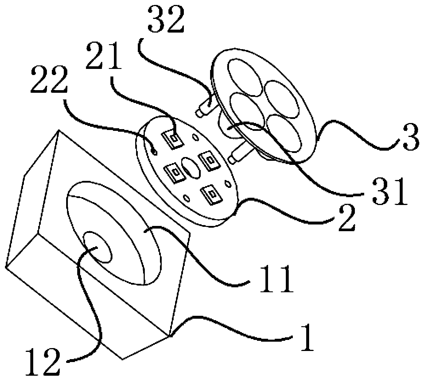
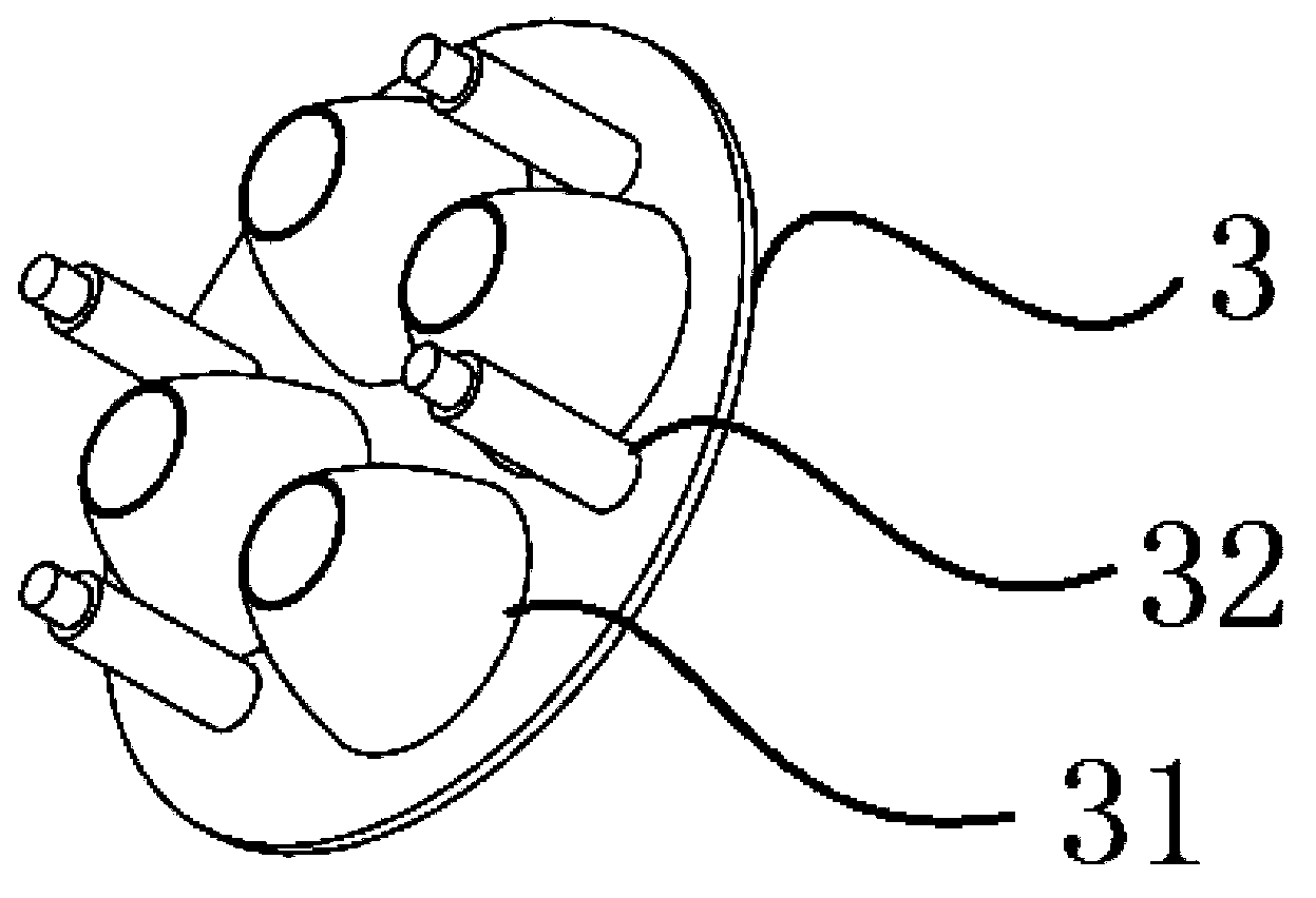
[0045] Such as figure 1 As shown, the lamp module of this embodiment includes a base 1 , an LED aluminum substrate 2 and an LED lens module 3 .
[0046]Wherein, the base 1 has an upper surface and a lower surface parallel to each other, and both the upper surface and the lower surface are quadrangular. The base 1 also has four sides, each of which is a plane and includes A pair of opposite sides parallel to each other on the upper surface and the lower surface. And in this embodiment, the four sides are all inclined surfaces, and the value of the complementary angle of the dihedral angle between each inclined surface and the upper surface is the same, and the specific value range is the light source The value of the light intensity in the light distribution curve ranges from an angle corresponding to two-thirds of the central light intensity of the light distribution curve to ninety degrees. In this way, the shape of the base 1 is specifically an inverted prism.
[0047] Th...
Embodiment 2
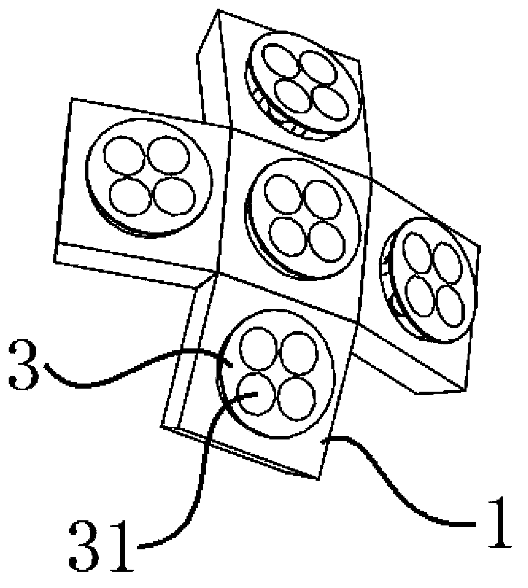
[0057] Such as Figure 4 and Figure 5 As shown, the difference between this embodiment and Embodiment 1 is: in this embodiment, the upper surface and the lower surface of the base 4 of the lamp module are both triangular, and the base 4 also has a groove 41 and a through hole 42. The functions of the groove 41 and the through hole 42 are respectively the same as those of the groove 11 and the through hole 12 in Embodiment 1, and will not be repeated here. The lamp of this embodiment is spliced by four lamp modules, and the three sides of each lamp module in this embodiment are also inclined surfaces, and the gap between each inclined surface and the upper surface The value range of the complementary angle of the dihedral angle is also the angle corresponding to when the light intensity in the light distribution curve of the light source is two-thirds of the central light intensity of the light distribution curve to 90 degrees. . Therefore, the lamp of this embodiment can...
Embodiment 3
[0060] The difference between this embodiment and Embodiment 1 is that in this embodiment, the lamp is formed by splicing at least one first lamp module and at least one second lamp module.
PUM
 Abstract
Description
Claims
Application Information
PatSnap Eureka turns technology decisions into work you can execute. Powered by our Innovation Knowledge Graph, it runs expert workflows across engineering, life sciences, materials and intellectual property. Get your review-ready output in minutes.


