
Meter-wave radar low elevation estimating method based on minimum redundancy linear sparse submatrix

A minimum redundancy, meter-wave radar technology, applied to radio wave measurement systems, instruments, etc., can solve problems such as poor array angle measurement performance, large estimation error, target positioning and tracking failure, etc., to achieve good angle measurement performance and low signal accuracy Effect of Noise Ratio Threshold

Active Publication Date: 2014-06-25
XIDIAN UNIV
View PDF3 Cites 10 Cited by
  • Summary
  • Abstract
  • Description
  • Claims
  • Application Information

AI Technical Summary

Problems solved by technology

Since the array elements are only distributed at both ends of the array, the signal information received by the array is greatly limited, and the angle measurement performance of the array is still poor under the condition of low signal-to-noise ratio.
[0008] At present, although the existing low-elevation angle estimation methods for meter-wave radar have improved the performance of low-elevation angle estimation to a certain extent, their estimation errors are still relatively large, especially at low signal-to-noise ratios, which leads to poor positioning or tracking of targets. fail

Method used


Image

  • Meter-wave radar low elevation estimating method based on minimum redundancy linear sparse submatrix
  • Meter-wave radar low elevation estimating method based on minimum redundancy linear sparse submatrix
  • Meter-wave radar low elevation estimating method based on minimum redundancy linear sparse submatrix

Examples


Embodiment Construction

[0029] refer to figure 1 , illustrating that the present invention is based on the minimum redundant linear sparse subarray metric wave radar low elevation angle estimation method, which includes the following specific implementation steps:

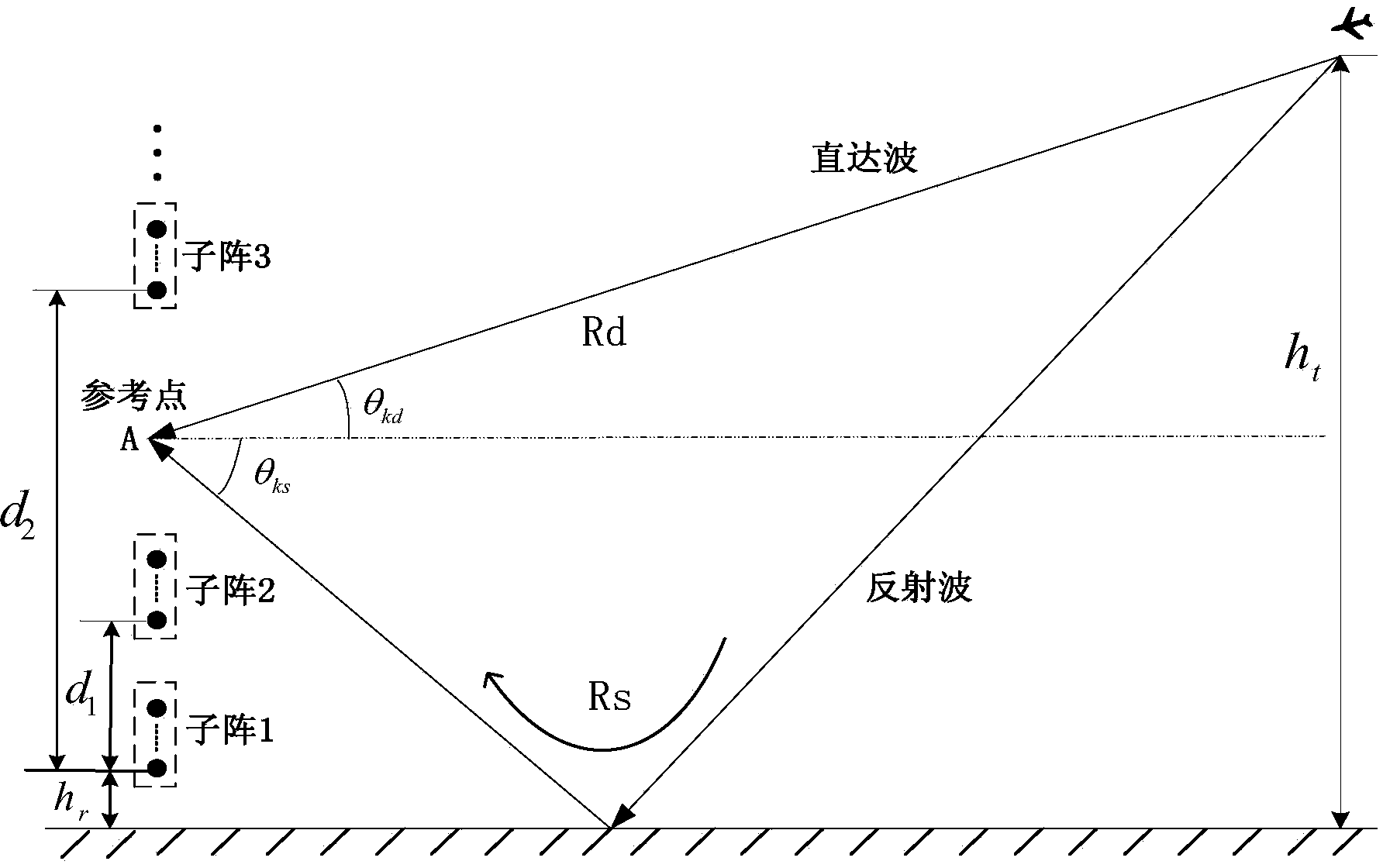
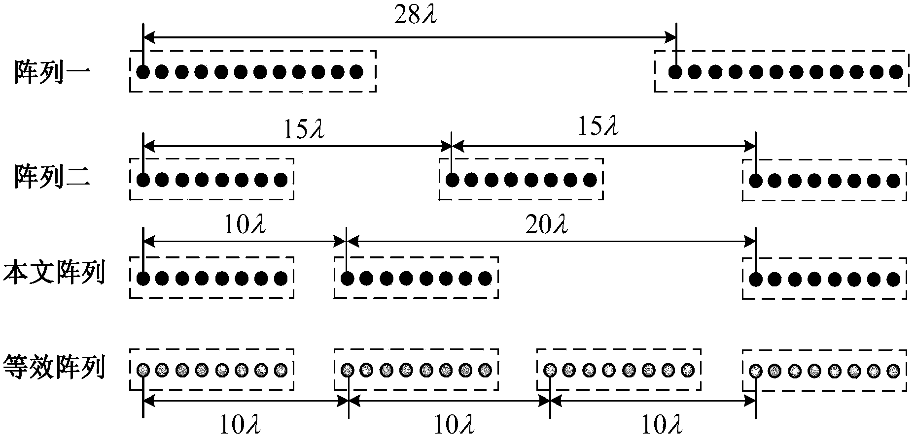
[0030] Step 1: Construct the minimum redundant linear sparse sub-array meter wave radar with P uniform linear arrays sparsely distributed in the form of minimum redundant linear arrays.

[0031] In the present invention, the minimum redundant linear sparse subarray meter wave radar and the low elevation angle target signal model are as follows figure 2 shown. figure 2 The P sub-arrays of the minimum redundant linear sparse sub-array meter-wave radar are sparsely distributed according to the minimum redundant linear array, each sub-array has a uniform linear array with the same structure, the number of sub-array elements is M, and the distance between the array elements in the sub-array is d(d≤λ / 2), λ is the wavelength of the incident ...


PUM


Abstract

The invention discloses a meter-wave radar low elevation estimating method based on a minimum redundancy linear sparse submatrix. The meter-wave radar low elevation estimating method based on the minimum redundancy linear sparse submatrix mainly solves the problem that errors of estimation of meter-wave radar low elevations are large in the prior art. The meter-wave radar low elevation estimating method based on the minimum redundancy linear sparse submatrix comprises the implementation steps of (1) structuring a minimum redundancy linear sparse submatrix meter-wave radar, (2) extracting target signals from radar echoes, (3) calculating auto-covariance matrixes of submatrixes and cross covariance matrixes among the submatrixes, (4) structuring an augmented matrix of whole array data covariance matrixes, (5) restoring the rank of the augmented matrix by applying a spatial smoothing algorithm of distributed submatrixes, (6) carrying out characteristic decomposition on the covariance matrixes to obtain signal subspaces, (7) obtaining direction cosine non-fuzziness coarse estimation, (8) obtaining direction cosine fuzziness fine estimation, and (9) solving the fuzziness of the fine estimation by using the coarse estimation to obtain low elevation estimation with high precision and without fuzziness. According to the meter-wave radar low elevation estimating method based on the minimum redundancy linear sparse submatrix, the aperture of the meter-wave radar is expanded, the threshold of the signal to noise ratio is lowered, the precision of the lower elevation estimation is improved, and the method can be used for positioning and tracking targets.

Description

technical field [0001] The invention belongs to the technical field of radar signal processing, and relates to low elevation angle estimation of meter wave radar, in particular to a method for estimating low elevation angle of meter wave radar based on minimum redundant linear sparse subarray, which can be used for target positioning and tracking. Background technique [0002] In recent years, with the development and application of a series of high and new technologies such as anti-radiation missiles, ultra-low-altitude flight, and stealth technology, the air defense radar systems of various countries are facing serious threats. Meter wave radar has natural advantages in anti-anti-radiation missiles and anti-stealth, so it has been widely valued by various countries and has achieved rapid development. [0003] Meter wave radar is mainly used in long-range warning. Its main task is to find space targets such as aircraft and missiles. The general range of action is several hu...

Claims


Application Information

Patent Timeline
IPC IPC(8): G01S7/41
CPCG01S7/354
Inventor 杨明磊陈伯孝武宇娟鲁加战王玉
Owner XIDIAN UNIV
Learn More