
A device that can reduce the ripple coefficient of high-frequency rectified power supply

A power ripple, high-frequency rectification technology, applied in the output power conversion device, electrical components and other directions, can solve the problems of decreased uniform plating ability, increased defective product rate, poor deep plating ability of the coating layer, etc., to eliminate pulse burrs, The effect of improved performance index and flat waveform

Inactive Publication Date: 2016-03-02
东莞市脉拓表面处理科技有限公司
View PDF6 Cites 0 Cited by
  • Summary
  • Abstract
  • Description
  • Claims
  • Application Information

AI Technical Summary

Problems solved by technology

In recent years, the high-frequency DC power supply has been widely used due to its advantages of high efficiency, small size, and low price. However, due to the lack of understanding of the rectifier ripple coefficient by the manufacturers and the drive of the interests of the manufacturers, most manufacturers produce high-frequency DC power supplies. The waveforms of high-frequency DC power supplies are very bad, and some even output in the form of pulsed rectangular waves.
If these devices are applied to some special industries, it will have a serious impact on product quality, causing problems such as poor deep plating ability of the coating, decreased throwing ability, waste of materials, etc., and the rate of defective products will also increase

Method used


Image

  • A device that can reduce the ripple coefficient of high-frequency rectified power supply
  • A device that can reduce the ripple coefficient of high-frequency rectified power supply
  • A device that can reduce the ripple coefficient of high-frequency rectified power supply

Examples


Embodiment Construction

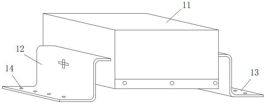
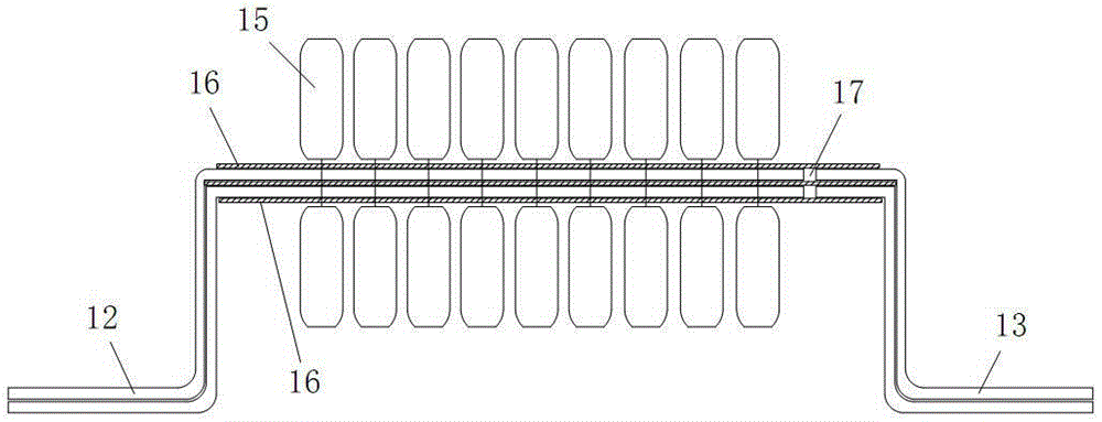
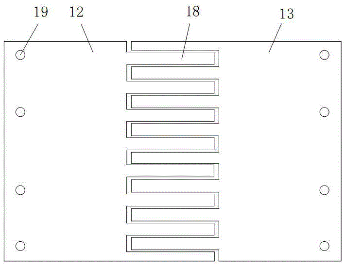
[0022] In this example, refer to figure 1 , figure 2 , image 3 , Figure 4 , Figure 5 with Image 6 , the device that can reduce the ripple coefficient of the high-frequency rectified power supply includes a capacitor group part 1 and an inductance group part 2, wherein the inductance group part 1 is installed at the positive electrode conductive copper bar 5 in the electroplating tank 3, and the capacitor group part 1 is connected across the Between the positive electrode copper bar 5 and the negative electrode conductive copper bar 4 in the electroplating tank 3, the inductance group part 2 is located closer to the power supply than the capacitor group part 1, and the current first passes through the inductance group part 2, then through the capacitor group part 1, and finally Then to the electroplating tank 3; the capacitor group part 1 includes a capacitor group shell 11, in which a positive electrode copper plate 12 and a negative electrode copper plate 13 are prov...


PUM


Abstract

The invention discloses a device capable of reducing high-frequency rectification power supply ripple factors. The device comprises a capacitor bank part and an inductor bank part, wherein the inductor bank part is installed at the position of a positive pole conductive copper bar in a plating bath, the capacitor bank part is connected between the positive pole conductive copper bar and a negative pole conductive copper bar in a crossing mode, the capacitor bank part comprises a positive pole copper plate and a negative pole copper plate, multiple capacitors are installed on the positive pole copper plate and the negative pole copper plate, the positive pole copper plate is fixed on the positive pole conductive copper bar, the negative pole copper plate is fixed on the negative pole conductive copper bar, the inductor bank part comprises a shell, and inductors are arranged inside the shell and located on the positive pole conductive copper bar in a sleeved mode. The device has the advantages that the peak valley difference value of a waveform becomes smaller after high-frequency rectification power supply currents pass through the inductor bank part, then the waveform becomes straight basically after the currents pass through the capacitor bank part, and in this way, low-ripple wave stable direct current output is provided for a load, and performance indexes, such as covering power, throwing power, cracking rate, hardness, wear resistance, brightness, current efficiency and voidage, of products are improved greatly.

Description

technical field [0001] The invention relates to the technical field of electroplating and electrolysis industry control, in particular to a device for controlling the waveform of electrolytic high-frequency DC power supply. Background technique [0002] DC power supply must be used in the electroplating and electrolysis industry. With the development of electroplating power supply, the power supply has experienced the development of batteries, electron tubes, transistors, thyristors, high-frequency inverters, etc., and the power waveforms are also quite different. In recent years, the high-frequency DC power supply has been widely used due to its advantages of high efficiency, small size, and low price. However, due to the lack of understanding of the rectifier ripple coefficient by the manufacturers and the drive of the interests of the manufacturers, most manufacturers produce high-frequency DC power supplies. The waveforms of high-frequency DC power supplies are very bad,...

Claims


Application Information

Patent Timeline
Patent Type & Authority Patents(China)
IPC IPC(8): H02M1/14
Inventor 王庆浩
Owner 东莞市脉拓表面处理科技有限公司
Learn More